Installation and assembly – MCZ Forma Wood 75 Dx User Manual
Page 24
22
4-INSTALLATION AND ASSEMBLY
made of a galvanised profile to prevent bearing the weight on the cladding components (wooden beams or marble lintels), which do not
have a freestanding structure in order to intervene easily in case of anomalies and/or future maintenance.
Dry mount the hearth of the cladding, leaving a 1 cm gap between the fireplace and the hearth for insulation. (fig.8)
FIREPLACE INSULATION
The closed fireplace must always be separated from the adjacent walls and ceiling.
If necessary use insulating materials to insulate the walls in contact with the unit, in case they risk being damaged or even catching fire
(walls made of wood, plaster board, etc...). (figure 8)
WOODEN BEAM INSULATION
The wooden beam must be protected with adequate insulation from the hot parts in order to prevent the risk of fire or damage to the
cladding (figure 9).
HOOD VENTILATION OUTLETS
It is mandatory to install the hood ventilation outlets of the manufacturer or outlets that can guarantee the same functions and the same
air passage section.
The manufacturer cannot be held liable for any damage caused to the structure or the electrical components if this precaution is not
complied with.
For proper room ventilation operation please note that:
• In the lower part of the cladding there must be a convective air inlet that must not be less than 400 cm
2
• In the upper part there must be an expulsion opening (in addition to the ducting outlets) of at least 230 cm
2
to free the residual heat
that accumulates within the cladding into the room (with the COMFORT AIR KIT this outlet is not necessary, because the heat inside
the cladding is indirectly aspirated by the fans themselves).
This allows to recover part of the structure heat that would otherwise be lost if left inside the cladding, whilst guaranteeing perfect
product operation.
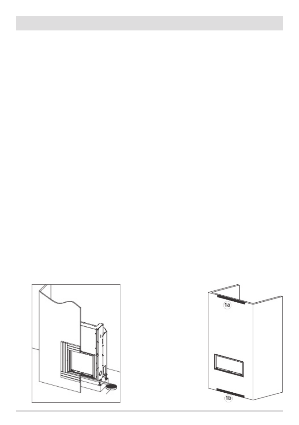
For a better understanding of the amount, size and function of the ventilation outlets to be installed on the cladding, illustrated below is
an installation example with the relative outlets.
1a) Grille for convection air release
1b) Grille for convection air input
Grilles 1a and 1b are essential for releasing the heat the collects in the hood and it is mandatory to fit them regardless of the type of
installation or cladding one must fit.
FIGURE 9 - INSULATION OF UNIT FROM WALLS AND
CLADDING