Ef e – MCZ Vivo 70 Wood User Manual
Page 17
Chapter 4
INSTALLATION AND USE MANUAL
page
17
Installation and assembly
Technical service – MCZ Group S.p.A. all rights reserved - Reproduction prohibited
A
A
E
E
E
F
E
D
C
C
C
B
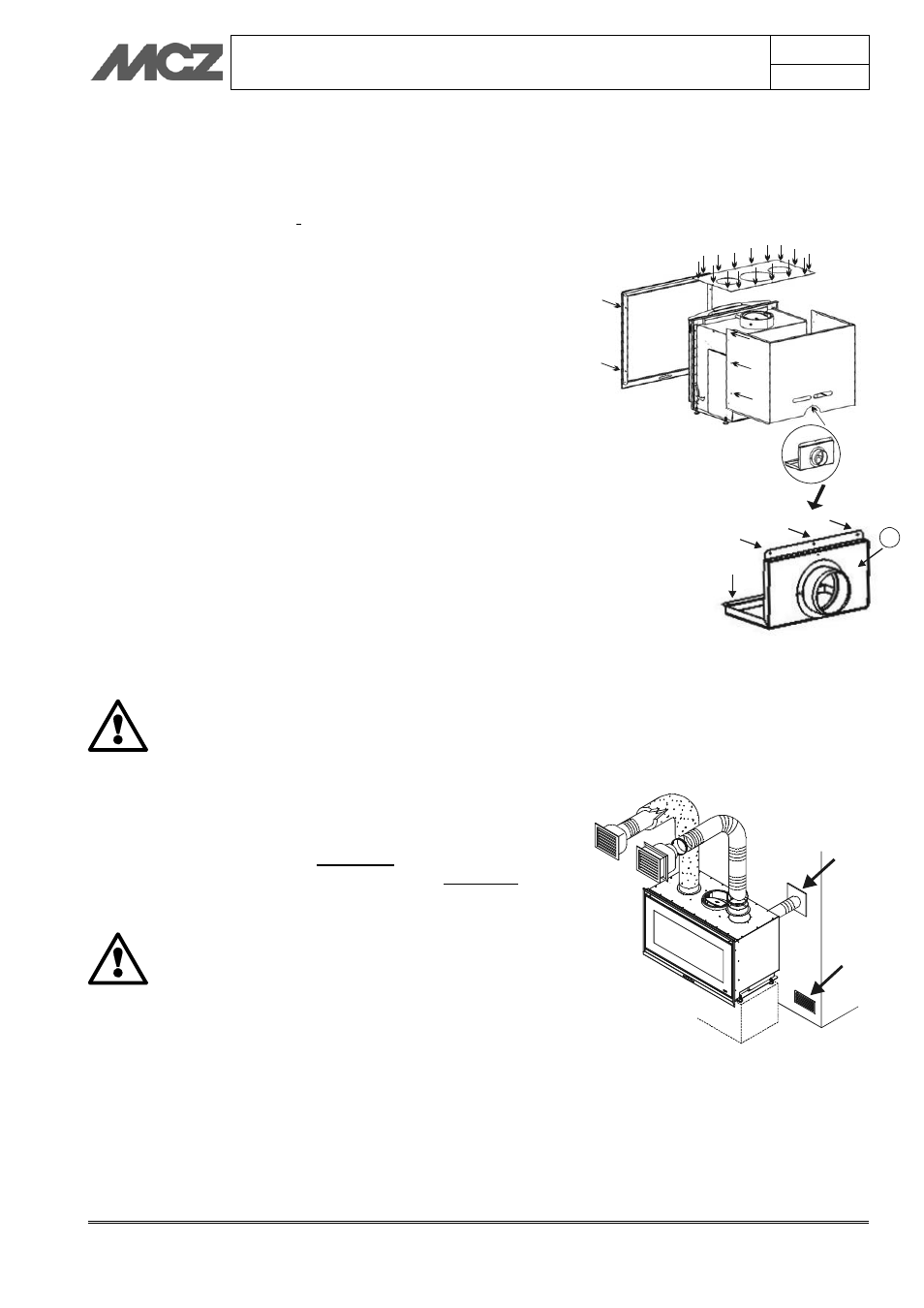
4.3. EXTERNAL AND INTERNAL AIR INTAKE
4.3.1. Combustion air inlet
The VIVO fireplace stove has a rear hole Ø 100 with a flange for entry
of air that is indispensable for combustion and proper operation.
This flange must be connected to the external air intake using
appropriate pipes (optional). The flange for ducting of the combustion
air intake normally faces the rear of the stove unit (as in the figure
alongside). However, it is possible to change its position and facing.
It is possible to remove the combustion air duct with flange Ø 100 and
to re-install it so that the flange faces downwards.
This option is
provided to favour connection if the air flow or the ducts come from
under the fireplace stove.
To perform this operation (figure 4):
1. remove the frame by loosening the two screws (A) on the right
and the two on the left
2. loosen the 16 screws (B) at the upper part of the stove unit
and remove the cover
3. loosen the 6 screws (C) on the right and left sides and the
screw (D) on the back and remove the entire cladding
4. loosen the 6 screws (E) of the duct with the flange (F) Ø 100
5. turn the duct (F) so that the flange Ø 100 faces downwards
6. Perform the steps in points 1-2-3-4 in reverse order
In the absence of this direct connection (B), it is obligatory to
install in the room (preferably in the cladding) an external air
intake A with a free passage surface of not less than 150 cm
2
.
FOR BEST OPERATION, MCZ STRONGLY SUGGESTS
CONNECTING THE COMBUSTION AIR INTAKE Ø 100
TO AN EXTERNAL AIR INTAKE OF AT LEAST TO DRAW
AIR FROM OUTSIDE THE CLADDING.
4.3.2. Air inlet for natural ventilation
If the fireplace stove is installed with natural ventilation, you must
provide an external air intake B (150 cm²) that allows natural fresh air
to flow inside of the cladding. This air intake A (150 cm²) must be
made in the room where the stove unit is installed (figure 5).
It is indispensable to comply carefully with this
instruction, otherwise the lack of oxygen may
compromise the safety of the installation.
4.3.3. Air inlet for forced ventilation
If the fireplace stove is installed with forced ventilation, i.e. using the
COMFORT AIR kit, place air intakes and ducts as follows:
an external air intake (150 cm²) must be provided that allows
natural fresh air to flow into the cladding. This air intake A can also
be located in the room where the stove unit is installed.
Figure 5 – Intake for external combustion air
and for natural ventilation
A
B
Figure 4 – Removal of the combustion air
duct