MCZ Vivo 70 Wood User Manual
Page 20
Chapter 4
INSTALLATION AND USE MANUAL
page
20
Installation and assembly
Technical service – MCZ Group S.p.A. all rights reserved - Reproduction prohibited
4.5. ADJUSTMENT OF HEIGHT AND BALANCING
The VIVO fireplace stove is equipped with adjustment feet that are
screwed into the stove unit, and have the purpose of levelling the fire
bed of the fireplace stove. They are therefore provided with a minimum
adjustment. (figure 8).
To adjust the feet you must slightly raise the stove unit, grasp with the
fingers the threaded part of the screw, and loosen or tighten to allow
levelling (the adjustment is about 1 cm).
Do not eliminate the feet. They are indispensable for levelling.
Removing the feet is considered a structural modification of
the product and therefore voids the guarantee.
If the floor is made of flammable material, the lower
part of the fireplace stove must be kept at least 200
mm from the floor.
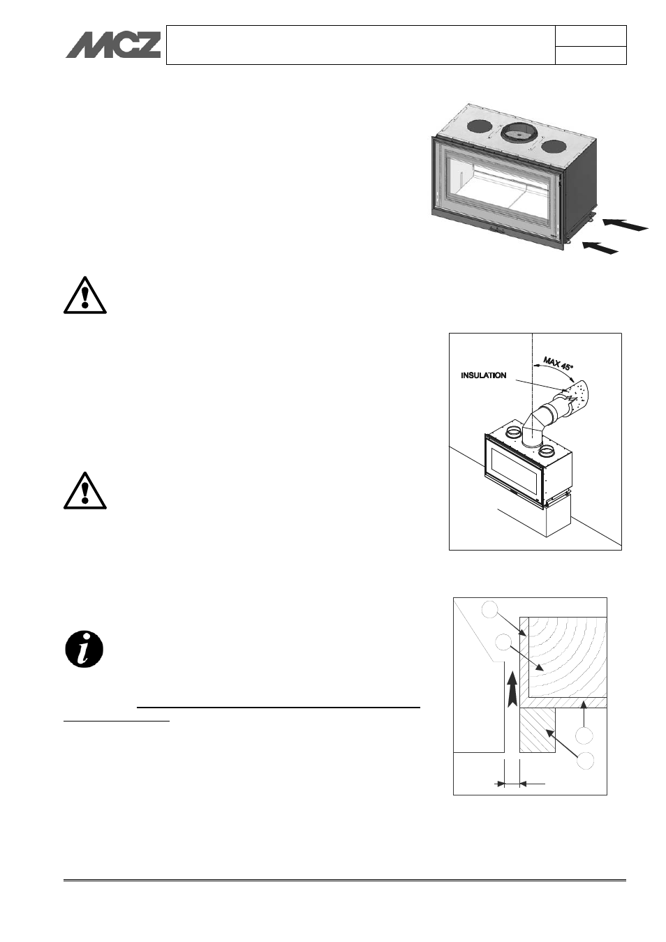
4.6. CONNECTION TO THE FLUE PIPE
We recommend connecting the stove to the flue pipe by means of pipes
and bends in aluminised steel, capable of withstanding the high
temperatures which are reached in that section of pipe, and of resisting
corrosion from the fumes. These connecting pipes are available on
request in various sizes (see our price list), and they simplify
installation, as they are assembled by fitting one into another. Figure 9
Any increase in the section of the connecting pipe
must start immediately above the hood of the
fireplace and not along the flue pipe section
When installation is complete, the smoke connection
must be insulated with ceramic fibre matting or
material that is resistant up to at least 600°C.
4.7. INSTALLATION OF CLADDING AND HOOD
LINER
BEFORE YOU START INSTALLING THE CLADDING OF
THE FIREPLACE STOVE, READ CHAPTER 5.2
“OPERATING TEST”
The fireplace stove and the parts of the cladding must be attached to
one another WITHOUT COMING INTO CONTACT WITH THE
STEEL STRUCTURE to prevent transmission of the heat to the marble
and/or stone, and to allow normal thermal dilation. use care with wood
finishes such as beams or shelves, which must be suitably insulated.
(Figure 12)
In particular, shelves must be placed at a distance of not less than 30
cm from the upper part of the unit.
We recommend making the hood liner in fire-resistant
plasterboard of 15/20 mm thickness, with a self-supporting frame in
galvanised profile, so as not put weight on components of the cladding
(such as wooden beams and marble architraves) which do not have a
load-bearing structure and to make it easy to work in the event of
future anomalies and/or maintenance.
Figure 9 – Connection to the flue pipe
THERMAL PROTECTION OF CROSSBEAM
1. Insulation applied or to be applied.
2. Wood beam
3. Marble or other material
1
1
2
3
10 mm
Figure 8 – Level adjustment feet
Figure 10 – Insulating a wooden beam