MEDC DB3B User Manual
Page 4
07/14
© MEDC 2014
Access to Terminals
On Ex d versions, the cover is secured with 6 off M5 cover screws (4.0mm A/F hexagon key). Once the cover
fixings are unscrewed, the cover can be lifted away from the enclosure to gain access to the interior. The cover
fixings are captive and will remain in the cover.
On Ex de versions the removable cover is secured using 3 off M5 cover screws (4.0mm A/F hexagon key). Once
the cover fixings are unscrewed, the cover can be lifted away from the enclosure to gain access to the interior. The
cover fixings are captive and will remain in the cover. All terminal screws, used and unused, shall be tightened
down.
Once termination is complete, carefully replace the cover assembly back onto the body, avoiding damage to the
mating surfaces. Tighten the cover screws evenly. On Ex de certified versions, ensure the maximum torque value for
the cover screws is observed, as marked on the Ex e cover. Ensure the O-ring is seated correctly on the cover
during re-assembly. On Ex d certified versions, ensure the required maximum gap of 0.04mm is maintained
between the cover and the base once assembled.
Wiring details
The unit is available in a number of basic configurations:
1. Ex d - AC input, single stage.
2. Ex d - AC input, dual stage with voltage-free stage selection.
3. Ex de - AC input, single stage.
4. Ex de - AC input, dual stage with voltage-free stage selection.
5. Ex d - DC input, up to 3 user selectable stages without monitoring.
6. Ex de - DC input, up to 3 user selectable stages without monitoring.
7. Ex d - DC input, up to 2 user selectable stages with EOL / monitoring (standard configuration).
8. Ex de - DC input, up to 2 user selectable stages with EOL / monitoring (standard configuration).
9. Ex d - DC input, up to 3 user selectable stages with optional EOL / monitoring (alternative configuration).
10. Ex de - DC input, up to 3 user selectable stages with optional EOL / monitoring (alternative configuration).
11. Ex d - DC input, 5 user selectable stages with voltage free stage selection with or without monitoring.
12.
Ex de - DC input, 5 user selectable stages with voltage free stage selection with or without monitoring.
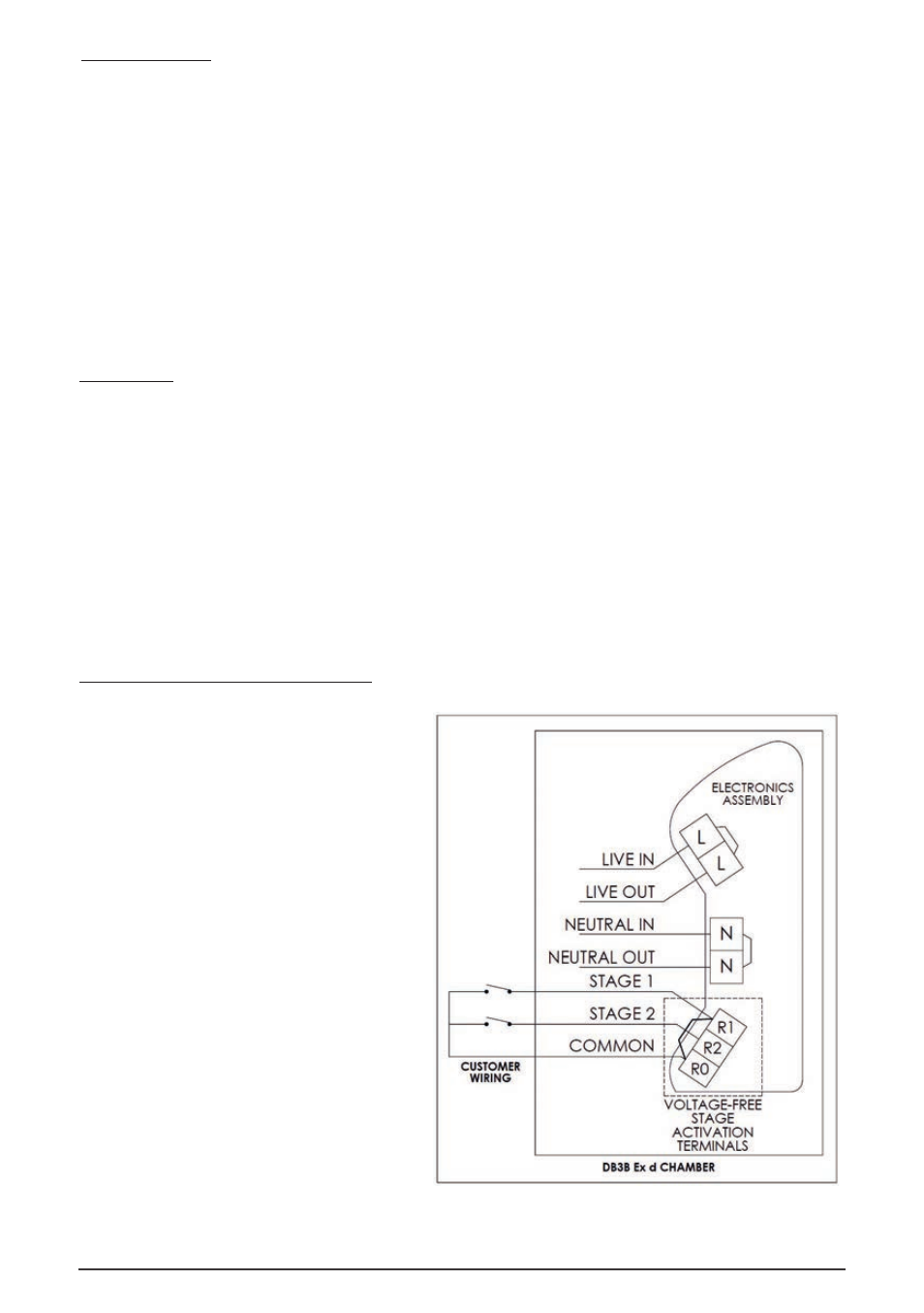
Ex d – AC input wiring details (Types 1 & 2)
•
Type 1: Connect the live and neutral
supply wires to the terminals as detailed in
the wiring diagram. The unit will be
supplied with the link between R1 and R0
fitted to the terminals. When power is
applied to the unit, the stage 1 tone will be
produced as selected on the 5- way DIP
switch.
•
Type 2: Connect the live and Neutral
supply wires to the terminals as detailed in
the wiring diagram. The unit will be
supplied with no link fitted between R1
and R0. Connect wires and remote
switches to terminals R0, R1 and R2 as
shown. When power is initially applied to
the unit, no tone will be produced. When
the switch connected to R1 is closed, the
stage 1 tone will be produced as selected
by the 5-way DIP switch on the electronics
assembly. When the switch connected to
R2 is closed, the pre-selected tone for
stage 2 is produced. See tone table 2 for
details of pre-selected tones.
Note: Closing both switches will produce no tone.