MEDC DB3B User Manual
Page 7
© MEDC 2014
07/14
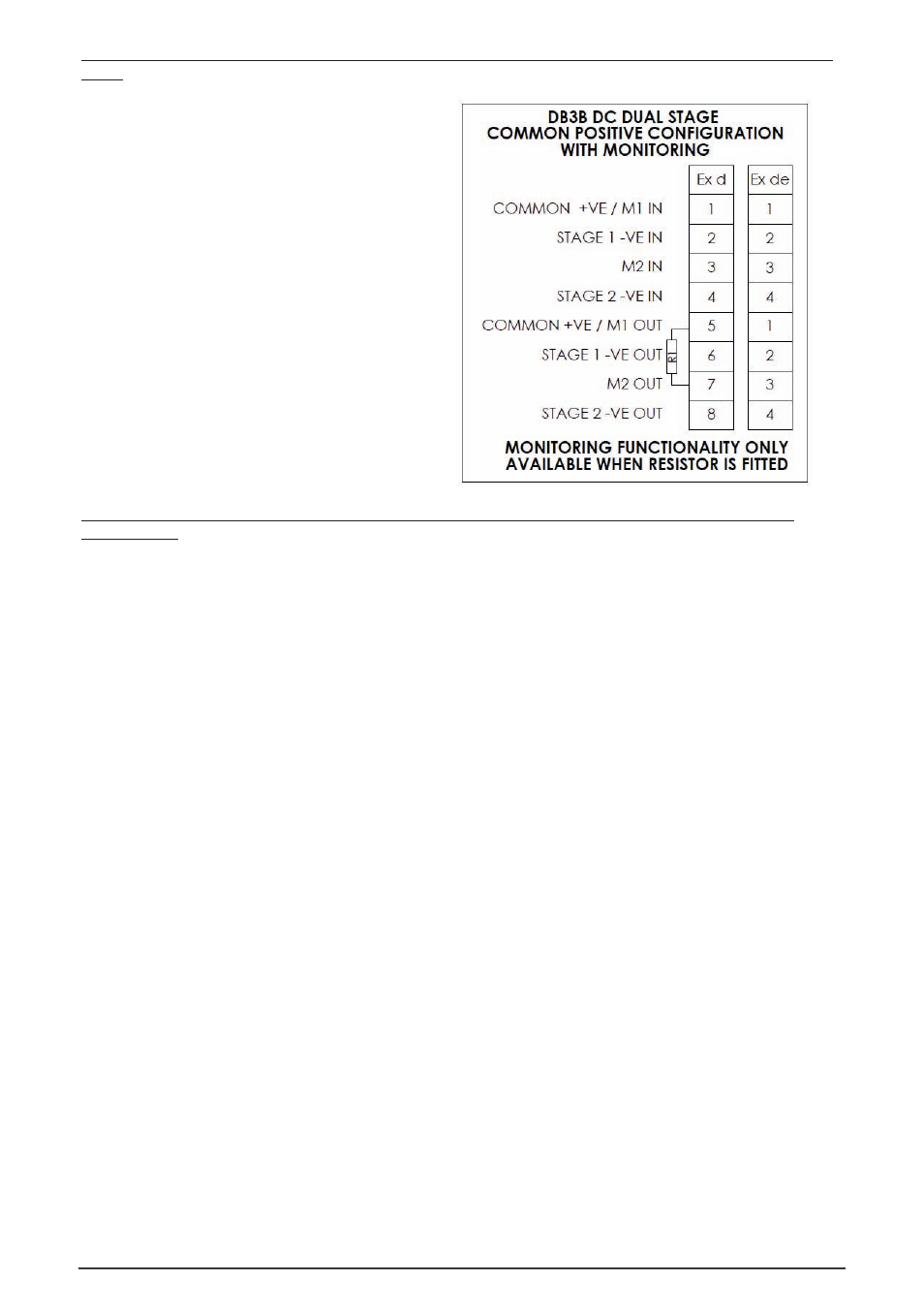
Ex d & Ex de – DC input, dual stage common +ve with monitoring (standard configuration) wiring details (Types
7 & 8)
Connect up to 4 supply wires to the terminals as
detailed in the wiring diagram. Stage 1 is
produced when power is applied across the
common +ve and stage 1 -ve terminals. Stage 2 is
produced when power is applied across the
common +ve and stage 2 -ve terminals.
Monitoring functionality is obtained when the
supply is connected across M1 & M2 terminals.
Note: monitored terminals are not polarity
dependent
Ex d & Ex de – DC input, up to 3 stage with or without monitoring (alternative configuration) wiring details
(Types 9 & 10)
Note: This alternative configuration must be specified when ordering the unit.
This type can be connected either as a three stage common –ve configuration, or if an optional EOL is specified if
can be configured as a dual stage common –ve system with monitoring.
•
4-wire system (Triple stage, Common +ve): Connect 4 supply wires to the terminals as detailed in the
wiring diagram (1 common +ve wire and 3 -ve wires). Stage 1 is produced when power is applied across
the common +ve and stage 1 -ve terminals. Stage 2 is produced when power is applied across the
common +ve and stage 2 -ve terminals. Stage 3 is produced when power is applied across the common
+ve and stage 3 -ve terminals.
•
4-wire system (Dual stage, common –ve with monitoring): Connect up to 4 supply wires to the terminals
as detailed in the wiring diagram. Stage 1 is produced when power is applied across the common -ve and
stage 1 +ve terminals. Stage 2 is produced when power is applied across the common -ve and stage 2 +ve
terminals.
Monitoring functionality is obtained when the supply is connected across M1 & M2 terminals. Note:
monitored terminals are not polarity dependent