Signal connections, Figure 9: flowmeter powered by external supply, Flowmeter (pulse output) – Precision Digital PD6300 User Manual
Page 22: Flowmeter (magnetic pickup coil)
Model PD6300 Pulse Input Rate/Totalizer
Instruction Manual
22
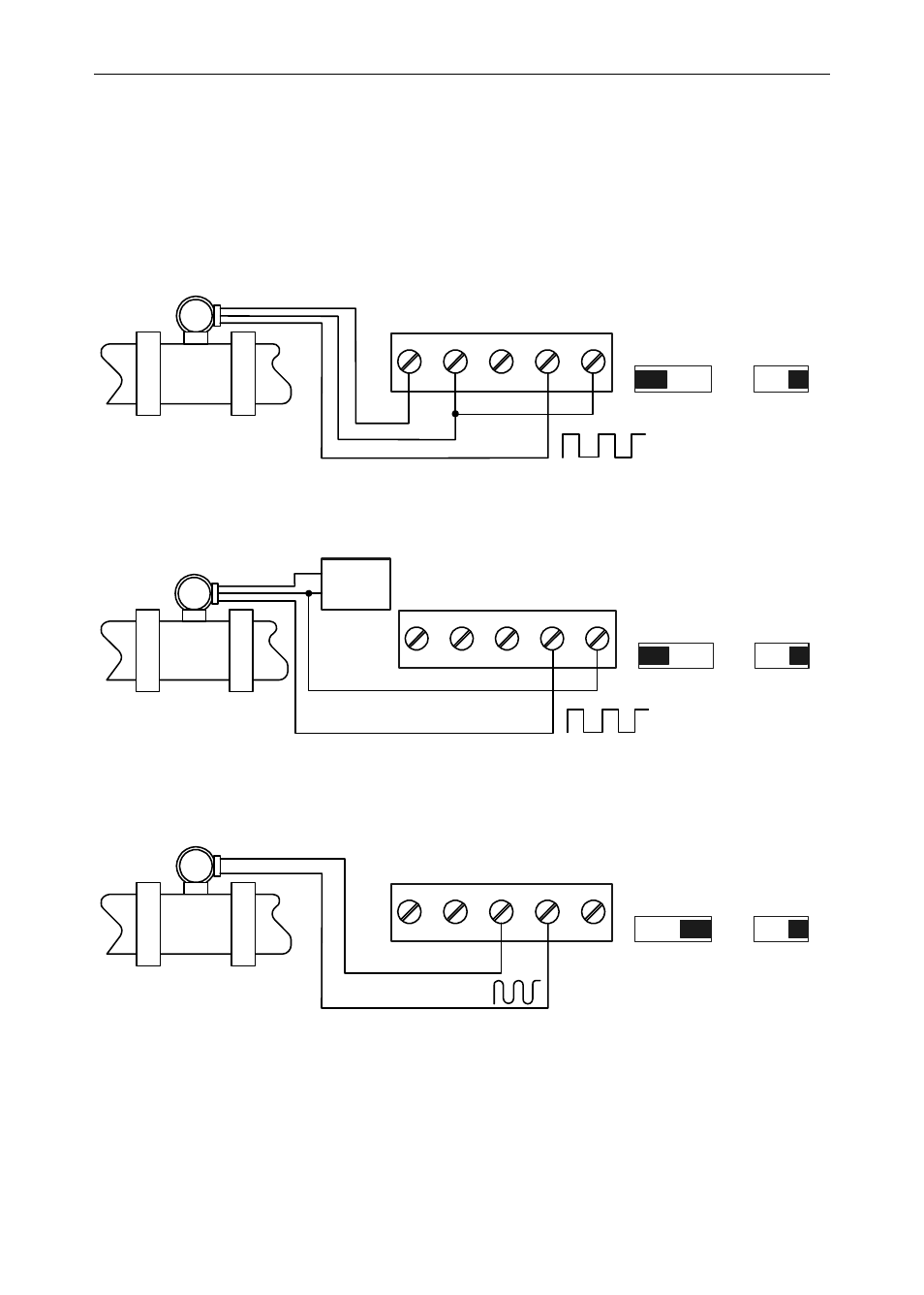
Signal Connections
Signal connections are made to a five-terminal connector labeled
SIGNAL on Figure 6. The COM (common) terminal is the return for the
input signals.
The following figures show examples of signal connections.
Setup and programming is performed through the front panel buttons.
Flowmeter
(Pulse Output)
S-
P-
2
1
3
5
4
P+
S+
COM
INPUT SIGNAL
V
PNP NPN
mV
LEVEL
TYPE
Figure 8: Flowmeter Powered by Internal Power Supply
S-
P-
2
1
3
5
4
P+
S+
COM
INPUT SIGNAL
V
PNP NPN
mV
LEVEL
TYPE
External
Power
Supply
Flowmeter
(Pulse Output)
+
-
Figure 9: Flowmeter Powered by External Supply
Flowmeter
(Magnetic
Pickup Coil)
S-
P-
2
1
3
5
4
P+
S+
COM
INPUT SIGNAL
V
PNP NPN
mV
LEVEL
TYPE
Figure 10: Self-Powered Magnetic Pickup Coil Flowmeter