RISCO Group Industrial LuNAR User Manual
Page 13
Advertising
Ind. LuNAR RK200DTG3 Installation
Guide
11
Insert the cable via the cable opening (Figure 4) and connect the desired wires as described in
“Step 4- Wiring”.
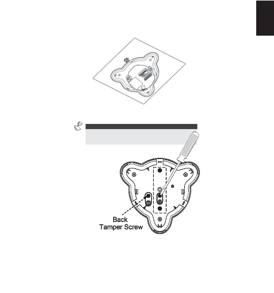
Mount the rear cover in its final location (Figure 5) using the 3 mounting screws and seal the
remaining open holes with sealant.
NOTE:
When a single gang box is used, use 2 additional
screws to mount the base to the single gang box.
The back tamper cannot be used in this case!
Return the PCB to its previous location and verify that it is well secured by the holding clips and the
screw.
FIGURE 4
FIGURE -5
FIGURE 5
Eng
lish
Advertising