Bus mode configuration (dip switch 6=on), Table 1: id settings for bus connection, 7not applicable (rc – RISCO Group Industrial LuNAR User Manual
Page 20: Communication
Ind. LuNAR RK200DTG3 Installation Guide
18
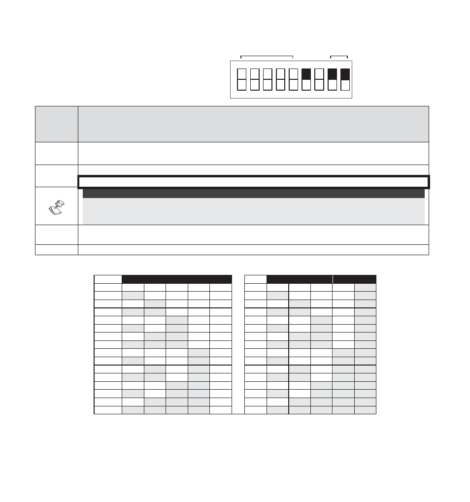
BUS Mode Configuration (DIP
switch 6=ON):
1
2
3
4
5
6
7
N/A
BUS
MODE
BUS ADDRESS
8
9
TAMPER
ON
DIP
switch
Number
Description
1-5
Used to set the detector ID number. (See Table 1)
Set the ID number in the same way as for any other ProSYS accessory.
6
Used to determine the detector’s connection mode.
DIP switch ON: ProSYS connection – BUS configuration
NOTE:
Upon power up or normal operation, the Ind. LuNAR RK200DTG3 waits 10 seconds for ProSYS
communication. Communication problem may occur due to bad wiring, wrong address, or ProSYS
not configured properly; RED LEDs will continuously flash until the problem is solved.
7
Not applicable (RC
communication
is automatically enabled when entering Walk Test mode in
the ProSYS and disabled otherwise).
8-9 DIP
Switch
ON: in order to enable the detector to report the tamper status to ProSYS.
Table 1: ID Settings for BUS connection
ID
1
2
3
4
5
ID
1
2
3
4
5
01
OFF OFF OFF OFF OFF
17
OFF OFF OFF OFF ON
02
ON OFF OFF OFF OFF
18
ON OFF OFF OFF ON
03
OFF
ON OFF OFF OFF
19
OFF
ON OFF OFF ON
04
ON
ON OFF OFF OFF
20
ON
ON OFF OFF ON
05
OFF OFF ON OFF OFF
21
OFF OFF ON OFF ON
06
ON OFF ON OFF OFF
22
ON OFF ON OFF ON
07
OFF
ON
ON OFF OFF
23
OFF
ON
ON OFF ON
08
ON
ON
ON OFF OFF
24
ON
ON
ON OFF ON
09
OFF OFF OFF ON OFF
25
OFF OFF OFF ON
ON
10
ON OFF OFF ON OFF
26
ON OFF OFF ON
ON
11
OFF
ON OFF ON OFF
27
OFF
ON OFF ON
ON
12
ON
ON OFF ON OFF
28
ON
ON OFF ON
ON
13
OFF OFF ON
ON OFF
29
OFF OFF ON
ON
ON
14
ON OFF ON
ON OFF
30
ON OFF ON
ON
ON
15
OFF
ON
ON
ON OFF
31
OFF
ON
ON
ON
ON
16
ON
ON
ON
ON OFF
32
ON
ON
ON
ON
ON