Remote Processing RPC-220 User Manual
Page 13
WRITING, DEBUGGING, AND SAVING PROGRAMS
SECTION 3
Page 3-2
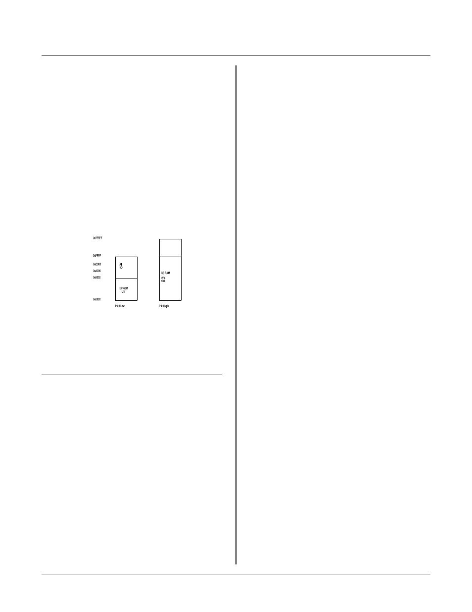
Figure 3-2 I/O and RAM Map
Code starting at 0x8000 should be exactly what you
would have if you were starting in EPRO M at address 0,
except there is an 0x8000 offset. Interrupts are handled
by the monitor by jumping to 0x8000 + interrupt base.
Change your C compiler start up code so it starts at
0x8000. If you ordered the development system, then
the code needed to use the Dunfield compiler has been
included. Simply install the Dunfield compiler first, then
replace the files with those on the supplemental disk.
These files are 8051RLPT .ASM , 8051RL PM. ASM, and
8 05 1R L P L. A S M .
The I/O map is more complicated because there are
more de vices to select. A ll I/O is accessible re gardless
of the setting of the d evelopm ent/no rma l mode bit.
Figure 3-2 is the external map.
E a ch a re a is se le c te d by th e fo ll ow i ng ta b le :
Device/area
Address
Flash EPROM
0x0000 - 0x7fff
Expansion port
0x8000 - 0x9fff
R e al ti m e c lo c k ( R T C )
0xa000 - 0xbfff
RAM segment
0xc000 - 0xffff
Several demonstration programs access I/O. Directories
where progr ams are located:
MEM 220
RTC
FLA SH
ACCESSING I/O AND RAM
I/O dev ices and RAM share the sam e addresses. Access
to them is controlled by CPU port P 4.0. When this line
is high, RA M is accessed using M OVX type comm ands.
W h e n t hi s l in e is lo w , t he e xp a ns io n po r t a n d r e a l t im e
clock are accessed.
NOTE: The I/O contr ol line, CPU port P. 0, should be
low for as short a period of time as possible.
Additionally, interrupts should be turned off
while the line is low especially if the routine
accesses external memory. The following are
suggested step s to using the I/ O por t.
1
Set up pointers and registers as necessary to perform
the I/O operation.
2
Turn off interrupts (if used)
3
Set CPU por t P4.0 low
4
Per form the read o r wr ite
5
Set CPU por t 4.0 back high
6
Enable interr upts.
Step 4 above may c onsist of several reads a nd/or writes.
The idea is to keep this time short.
Altern ately, you could w rite inter rupt ser vice routin es to
check the I/O line before accessing RAM . The line
would be r estored a fter ser vicing. The r eason this
m e th o d i s n o t r e c om m e n de d is th e am o u nt of ti m e
needed to read, store, and restore the status is longer
than the time it takes to code str aight throu gh. If step is
4 long (say monitoring a clock status bit), perhaps the
extra ove rhead m ight be wor th it.
S e e t he M E M 2 20 . C p ro g ra m to se e ho w RA M a nd I/ O
are accessed. Specialized speek and spoke functions are
written in assembly language. This wa s done not only to
s p ee d up m e m or y a cc e ss a nd r e du c e i nt e rr u p t o f f t im e
but to ensure correct access. N ote that parameters to the
function are passed in the stack and returned in registers
A and B. Make sure your compiler passes parameters
through the stack in the memory model you are using.
You may have to adjust parameter passing for your
compiler.
MONITOR ROM
The monitor ROM allows you to download code, set
breakpoints, exam ine and modify RAM and I/ O. T he
monitor occupies the same space as the final program
will. Generally, the final code replaces the
monitor when the project is done. T he monitor can be
re-installed under tw o conditions:
1
Your code allows the flash to be written to. This is a
routine that must be included in your program. See
" S A V IN G Y O U R P R O G RA M T O F L A SH " .
2
The flash is removed from the socket and
programmed using an external programmer.