Remote Processing RPC-220 User Manual
Page 21
SERIAL PORTS
SECTION 4
Page 4-1
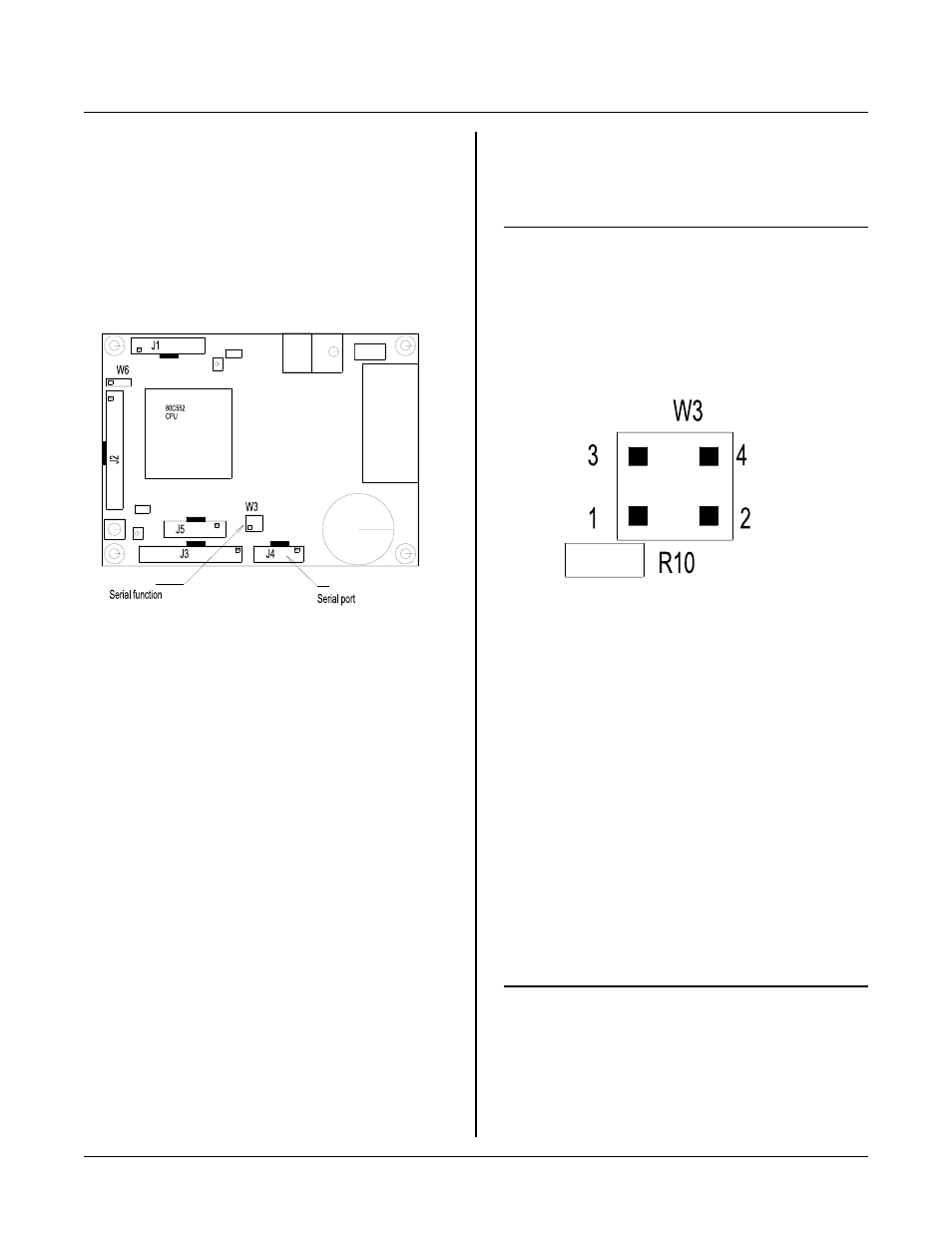
Figure 4-1 Serial Port Jumpers and Connectors
Figure 4-2 Jumper W3 Pin Num bering
INTRODUCTION
SERIAL PORTS
S E C T IO N 4
The RPC -220 has 1 hardware serial port. A second
software serial port is available. If the second port is not
needed, then these lines may be used for CTS/RTS
control on COM 0 or high voltage I/O to external
devices such as proximity sensors. The second serial
port is useful for sending to printers, displays, and other
non-time c ritical device s. Jum per block W3 is used to
enable C TS/ RTS or the second se rial por t.
COM 0
COM 0 is a hardware UA RT directly from the C PU. It
may be p rogr amm ed in any num ber of m odes. Refer to
the 80C552 data sheet file "8XC552OV.PDF" for more
program ming inform ation on the different mod es.
All demo programs use COM 0. M ost operate the serial
port in polled mode. SERIA L/S ERIN T. C oper ates in
interrupt mode. Timer divider factors for different baud
rates are also given.
When using timer 1 as the baud rate generator, be sure
to initialize TL1 and TH1. When T L1 is not initialized
there is a delay before the first character is sent out after
a power up or r eset. Usually, this is not a problem. But
if the first character must start right after reset, then TL1
must be initialized. T he delay could be 30 m illi-seconds.
Control Lines
Software CTS and RTS lines are available. These lines
are shared with other functions and ports on the card.
CPU ports P4. 3 and P4.4 ar e used for CTS/ RTS,
TX1/ RX1, or general purpose I/ O at CPU port J3.
Jumper W 3 connects the CPU to the RS-232 port U9.
Set the jumpers according to the table below.
W 3
CPU
Function
port
W3[1-2]
P 4. 3
CTS or T x1
W3[3-4]
P 4. 4
RTS or Rx1
The large F igure below, 4-2, show s W3 pin locations.
Square pad pin 1 is viewed from the component side.
SOFTWARE SERIAL PORT
J4 is also a second software serial port. These lines may
be used as CTS and/or RTS for COM 0. If one or more
of these lines is used for COM 0, then the software port
is not available.
Transmit and receive lines are taken from J4-4 (Receive)
and J4-6 (transmit). When using COM 0, these lines
must be broken from the cable.
Jumper W3 must be set to use either or both lines. Lines
P4.3 and P4.4 come from the CPU and also go to CPU
port J3. Set W3 as follows:
W 3
CPU
Function
port
W3[1-2]
P 4. 3
CTS or T x1
W3[3-4]
P 4. 4
RTS or Rx1
Review F igure 4-2 for jum per pin locations.