Remote Processing RPC-220 User Manual
Page 8
SETUP AND OPERATION
SECTION 2
Page 2-2
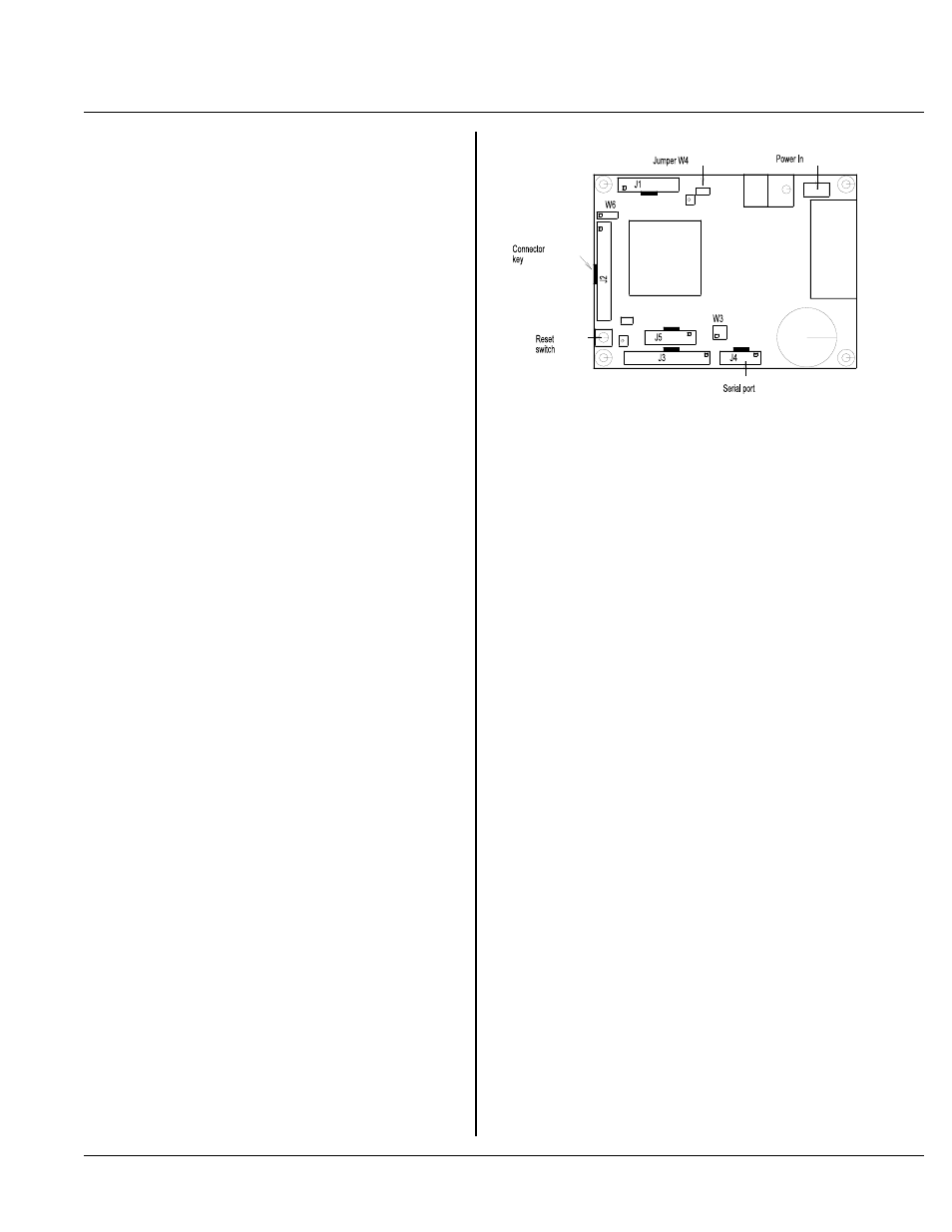
Figure 2-1 Start up connector locations
An inconvenience using some of the Microsoft Windows
editors is a lack of line number indication. Should you
ever make an er ror wr iting C code, the compiler r eturns
the line numbers of the error(s). Using a DOS editor,
such as "Edit", you can quickly go to the offending line.
Wordp ad or No tepad do not show you line num bers.
Wor d indicates the line on a page. Also, Wor d tends to
leave the file it is editing open. When it is open, the
compiler cannot access it. You will need to save and
close the file before compiling. Wordpad or Notepad do
n o t h a ve th is p ro b le m .
FIRST TIME OPERATION
Become familiar with the locations of connectors before
getting started. See Figure 2-1. RPC-220 jumpe rs have
been set at the fa ctory to op erate the system im mediately
using a 6 - 21 V supply. If you have a
5 V su p pl y, t h en r e mo v e j um p e r W 4 . F o r fi r st ti m e
operation, do not install any connectors or parts unless
specified belo w. Jumper s should be kep t in default
positions.
1.
Connect power.
The RPC -220 needs + 5 volts or 7 to 21 volts at 300
ma. T he RPC-220 has its own regulator which
supplies 5V to the rest of the card w hen powe r is
applied to the ' V' termin al.
Be careful when using "switching" power supp lies.
Some supplies do not regulate properly unless they
are adequately loaded.
Make sure pow er is off. Conne ct the powe r supply
to one of the appropriately marked terminals on the
RPC-220. Power connector P1 is designated as '5'
for 5 volts, ' V' for the 6-21 volt input, and ' G' for
ground.
2.
Connect the ser ial ports.
Connect one end of the VTC -9F connector to the 10
pin ' COM ' port (J4) on the RPC-220. The VTC -9F
' key' on the 10 pin connector faces the inside of the
card. Refer to Figure 2-1 for connector location.
Connect the DB-9 end to the PC's COM1 or COM2
port. You m ay need a 9 p in male to 25 pin female
adapter . T he VT C-9F is designed to plug directly
i nt o t he 9 pi n s e ri a l p o r t c o nn e ct or o n a P C .
Start up your serial communication program. Set
comm unication par ameter s to 19200 bau d, 8 data
bits, no parity, 1 stop. If using Microsoft Windows
Ter minal, you may load up ' mon220 .tr m' file
(located on the applications disk r oot directo ry) to
quickly configure the program. M ake sure you set
the "connector" to C OM1 or COM 2 in the
Communications window.
3.
Power up.
Turn on or connect the power supply. On power up
a message is printed.
Remote Processing Debug Monitor
For RPC-220
Version 1.0
If a nonsense message appears, your terminal or PC
may not be set to the appropriate communication
parameters. If the system still does not respond,
refer to TRO UBLESH OOTIN G later in this section.
4.
Testing.
Press the "Enter" key on your PC to verify the '> '
symbol returns. Type the letter "h" to view the
monitor help menu. If the system responds, you are