Remote Processing RPC-220 User Manual
Page 43
EXPANSION PORT
SECTION 14
Page 14-1
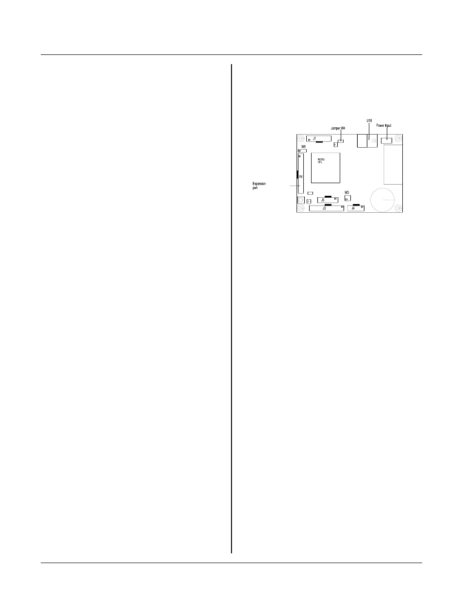
Figure 14-1 Pow er Input, Jum per, and
Expansion Connectors
EXPANSION PORT AND POWER
SECT ION 14
INTRODUCTION
E x pa n si on p or t at J2 a ll ow s yo u to c on n ec t o th e r I / O
type cards for expanded capability. Power connector P1
is for ground, + 5, and h igher voltage inputs.
EXPANSION PORT
Keep the connector length between J2 and expansion
card connectors as short as possible (4 inches or less).
Power and ground are available at this connector. Since
the ribbon cable is small gauge and has high resistance,
keep power curr ents as low as possible (less than 100
ma) to prevent ground loop problems. Ground loop
problems m anifest themselves as ran dom rese ts, lockups,
and inaccurate A -D read ings.
J2 expansion port pin out is sh own at the e nd of this
chapter.
EXTERNAL POWER
The RP C-220 accep ts different voltage range s,
depending upon the card. Recom mended operating
voltage is 5 ±0.25V, and is standard for a ll cards.
Absolute maxim um "5 volt" supply to the card is 6 volts.
This means you can hook up 4 ni-cad, car bon-zinc, or
alkaline batter ies to the 5 volt input.
Higher voltages are applied to the ' V' terminal on P1.
Jumper W 4 to connect regulator output to the rest of the
c a r d. E x t er n a l v o lt a ge s of 6 to 1 6 v o lt s a r e fo r P / N ' s
1715 and 1720. 5. 4 to 21 volts apply to P/N 1710 only.
Higher voltages may be applied provided a heat sink
under U10 is used. See "Heat Sink" below . Oper ating
current is 100 ma for the low power board (P/N 1710)
and 160 ma for others.
Board + 5 and gro und are applied thr ough appr opriate
pins at J2, J3, J4 or P 1.
P/ N 1710 h as rever se voltage pr otection if pow er is
applied to externally. The board itself does not have 5V
reverse protection.
The maximum external voltage of 16 or 21 volts is due
to regulator power dissipation (see "Heat Sink" below).
Up to 30 vo lts may be a pplied if an ade quate heat sink is
used under voltage regulator U10. The voltage may be
stepped down fr om higher v oltages yet (up to 40 volts)
by putting a regulator (such as a 7824) to P1.
Depending upon the external voltage, you may need a
heat sink on the extra regulator.
Heat Sink
A heat sink under U10 is normally not necessary.
Conditions when you need a heat sink depend upon the
amount of power you expect U10 to dissipate and
ambient temperature.
First ste p is to determ ine the pow er you e xpect U1 0 to
dissipate. T his is calculated as follows:
P(MA X) = (V
BATT
- 5) * I
Where: V
BATT
is battery or supply voltage
I = current into the board.
Current into the board depends upon its model number.
Use 100 m a for P/ N 1710 and 170 m a for all others.
Don' t forget to add current for other devices connected
to the bus, I/O por ts, LC D display, and if you are taking
power from the regula ted output.
No heat sink is necessar y if power( P (MAX ) ) is less
than 1.6W and the board oper ates at 25°C. T his means a
21 volt supply ca n be used w ith P/ N 1710 a nd 14 volts
with all other models (a ssuming no additional cur rent is
used).
There is a small heat sink on the RPC-220. In marginal
situations, you can screw down U10 to the board to get
slightly better heat dissipation.