Introduction, Display pin outs, Contrast/angle adjustment – Remote Processing RPC-220 User Manual
Page 40
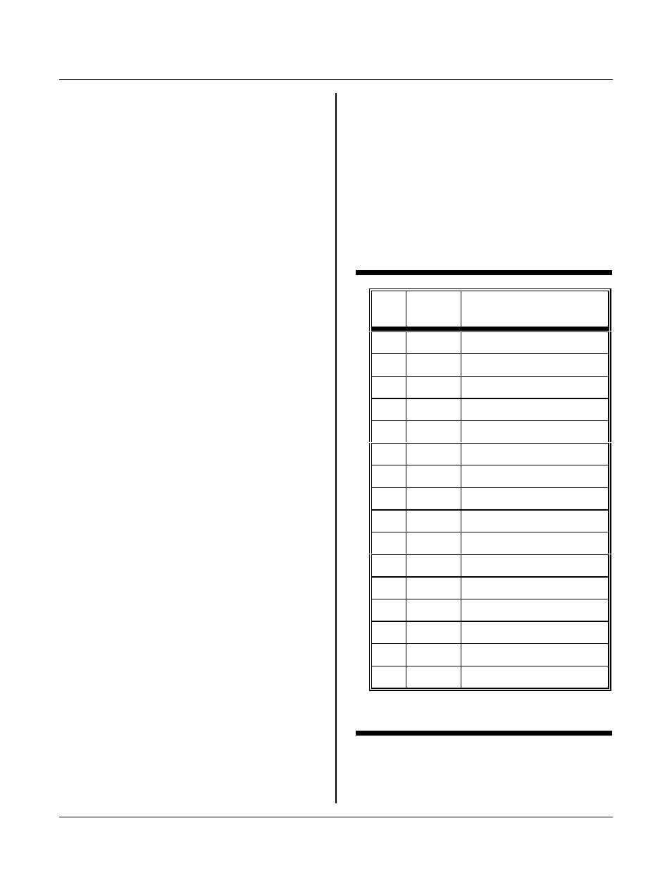
DISPLAY PORT
SECTION 13
Page 13-1
J5
pin
CPU
Line
LCD function
1
P 1. 2
Data
2
P 1. 3
Data
3
P 1. 0
Data
4
P 1. 1
Data
5
N C
no connect
6
N C
no connect
7
N C
no connect
8
N C
no connect
9
P1. 6*
Read/write (0 = write)
10
P 3. 4
E signal strobe
11
none
Angle/c ontrast adjust
12
P1. 7*
Register/data select
13
none
+ 5V
14
none
Ground
15
N C
no connect
16
P 1. 4
Enable 2
* CPU lines are open drain.
Table 13-1
LCD Port J5 pin out, C PU line, and function
DISPLAY PORT
SECT ION 13
INTRODUCTION
Port J5 supports character L CD' s and some VF displays
in 4 bit data mode. Seven lines from CP U port 1 and
one from C PU por t 3 are used to control the display.
Angle/contrast adjustment via R9 is provided as are
+ 5V and ground. Figure 13-1 on the next page shows
the location of the connector and R9.
CPU I/O lines for the display are shared between J3 and
J5. See Table 13-1 for a list of CPU lines used.
Any number of char acter displays may be used.
Prog ram example s assume a HD 44780 contr oller is
used. This controller is used on Optrex, AND , Stanley,
and other displays. Some VF displays from Noritake are
LCD interface compatible.
DISPLAY PIN OUTS
Pin outs for a size and type of LC D ar e gener ally
standard. However, pin outs for different display sizes
are not. The m echanical pin out for a 4 x 40 display is
different from a 4 x 20, which is different from a 2 x 20.
S o m e a r e du a l 1 6 pi n, o t he r s a r e du a l 1 4 pi n, a n d s o m e
are single line 14 pin. To further complicate ma tters,
the numbering scheme changes whether you take the
signals from the top or bottom of the display.
Electrically, all of these displays are the same or very
similar.
The following tables are pin outs for J5 on the RPC-220
and the two most popu lar display ty pes. Table 13- 2 is
for a 4 line by 40 character display. Table 13-3 is for
most other displays. This table is usually valid for 14
pin displays.
J5 pin out was optimized for a Optrex 4 x 40 display. A
simple 16 p in IDC connector from J5 to the display is all
that is needed. T he connector fr om this display must
mount on the bottom o f it.
Other 14 pin, dual in line displays m ay also dire ctly
connect using a simple IDC connector. The display
connector mounts on the top side and the ribbon ca ble is
reversed (display pin 1 goes to pin 14 on J5 side).
Connector Orientation
J5 is an open header connector. Pins 1 and 2 are marked
on the board. A s a further aid, a " key" outline is also on
J5.
CONTRAST/ANGLE ADJUSTMENT
Pot R9 is used to adjust display contrast and viewing
angle. Its location is shown in Figure 13-1 on the next
page. The pot is adjusted to 0V at the factory. Its range
is approximately + 5V to -7V, depending upon cur rent
draw.
Adjust R9 for the best display after it is initialized. Use a
3 mm slot screw driver.