Digital and opto ports chapter 6 – Remote Processing RPC-30 User Manual
Page 22
DIGITAL AND OPTO PORTS
CHAPTER 6
Page 20
RPC-30
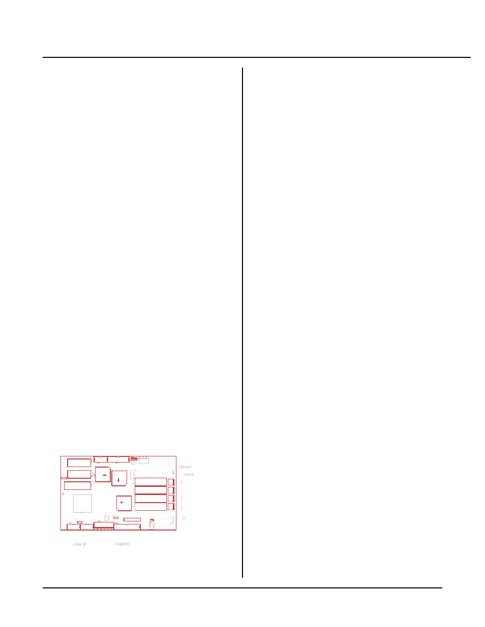
Figure 6-1 Digital I/O
INTRODUCTION
Digital I/ O lines ar e used to inter face with op to-module
racks, switches, low current LED's, and other TTL
devices. The RP C-30 ha s 24 of these lines a vailable
through J3. 8 of these lines are high cur rent outputs,
capable of sinking 75 to 200 ma. Additionally, there are
4 opto-module sockets on the card itself.
On-car d opto-mo dule slots accep t G4 and G 5 series op to
modules. G 4 series opto modules are used to sense the
p r e se n ce o f A C o r D C vo lt a ge s or s w it c h t he m .
Maxim um switching cur rent is 3 amper es.
G5 series are optically isolated analog input or output
modules. The modu les connect to therm ocouples,
RTD' s, load cells, 4-20 ma current loops, and general
purpose voltage inputs. They can also output voltages
and currents. These modules are supported by the AIN
and AOT comm ands. Input modules return a number
f r om 0 to 5 11 in a m an n er s im i la r to a n A - D .
Conversion time is about 1 milli-second.
In addition to the 24 I/O lines from J3, the display and
keypad por ts can be used as digital I/O . R efer to
chapters 8 and 9 for more infor mation.
WARNING:
Apply power to the RPC -30 before applying a
voltage to the digital I/O lines to prevent current
from flowing in and damaging devices. If you
cannot apply power to the RPC-30 first, contact
technical support for suggestions appropriate to your
application.
This chapter is divided into two sections. T he first
section refers to the on-card opto rack. T he second
section refers to the digital I/O port J3.
ON-CARD OPTO RACK
Description
The on-c ard opto r ack accep ts the popular G4 ser ies opto
modules (manufactured by Opto-22, Grayhill, and
others). These modules can switch AC or DC voltages
from 12 to 240 volts at 3 amperes. They can also sense
input voltages of the same type and range.
The RP C-30 also accepts the G rayhill G5 ser ies. T hese
modules m easure voltage, curr ent, therm ocouple outp ut,
or RTD resistance and return it as a frequency.
Additionally, modules c an output a volta ge or a c urre nt.
CAM BASIC supports the G5 series through the AIN and
AOT comma nds.
Installation
T h e G4 a nd G 5 m o d ul e s a r e in s ta l le d in th e sa m e
manne r as an op to rack. A scre w at the top is use d to
secure the module to the board. M odules may be
installed in any order and types can be intermixed.
A hole for a standoff nea r the m odules is pro vided to
keep the board from bending during installation or
rem oval.
Input and output lines are fastened by the two position
terminal in front of the appropriate opto module.
Refer to the appropriate module data sheet for additional
hookup information.
G5 operation
G5 modules may be used as inputs or outputs. Output
modules m ust be installed on a n externa l opto rack . Its
use as an input is disc ussed first.
Values from G5 m odules are returned using the AIN
function. The syntax is
A = A I N (slot)
The slot number is from 0 to 3 or 100 to 123,
corresponding to the position on the board or external
opto rack . T his function r eturns a n umber from 0 to
511, corr esponding to a resolution of 9 bits. The A IN
function takes about 1 ms to convert the input data.