Chapter 8 display port – Remote Processing RPC-30 User Manual
Page 29
CHAPTER 8
DISPLAY PORT
RPC-30
Page 27
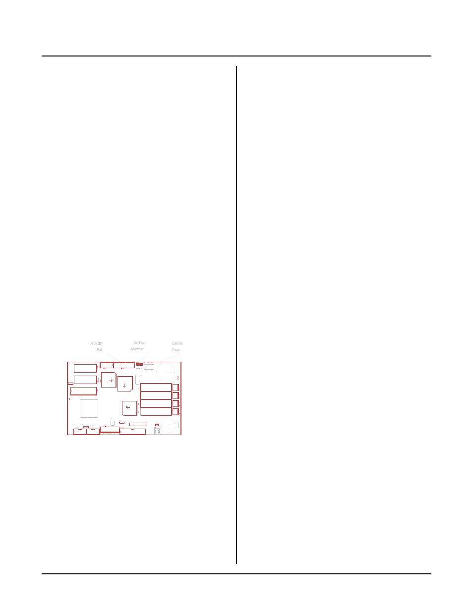
Figure 8-1 Display port
INTRODUCTION
CAM BASIC and the RPC -30 can interface to a wide
variety of displays:
VF (vacuum florescent) character
LCD (liquid crystal) character
LCD gr aphics
Character display sizes range from two lines by 20
characters to four lines by 40 characters. The graphics
display supports 160 x 128 pixels. Remote Processing
can supply these displays with appr opriate cables.
A contrast adjustment for LCD displays is built into the
card. All displays con nect to J4. An appr opriate ca ble
connects a display to the RPC-30.
If a display is not used, J4 may be used for general
purpose digital I/O. P ort A and part of port B from an
82C55 are available.
The cable length to a display depends upon the amount
of current it requires. A significant amount of voltage
drop occurs with a long cable. VF and LC D graphics
c a bl e s s h ou ld b e l es s t ha n 2 f e et . A c ha r a ct e r L C D
display cable sh ould be less than 5 feet.
CONNECTING DISPLAYS
The display port is designed to supply all the lines
necessar y for V F and L CD displays. A custom cable
connects the RPC-30 to the display.
Displays purchased from Remote Processing include a
cable. You simply connect the 20 pin connector to the
RPC-30 L CD display port and the other end into the
display.
Additional w iring is usually r equired for LC D gr aphic
and VF character displays. This information is included
with the display. Information content is display
dependent. Below is general information on both.
Graphic displays require additional voltages not
generated on the RPC-30. These must be supplied
externally. An external contrast adjustment may be
necessary.
WARNING:
P W R and ADJ silkscreen on the RPC-30 card are
reversed. Apply power to the terminal mar ked ADJ
(DP and LC D-5003). C onnect the wiper from the
contrast adjust to the terminal mar ked P W R (for
LCD -5003 or other graphic displays only).
VF char acter displays require + 5 volts and ground to be
brought to connector P6. This may be in the form of
external wires from the m ain power connector on the
board. The reasons power is not supplied are:
1.
The display requires 400-600 ma for oper ation.
By switching voltage through an opto module,
power to the display is controlled.
2.
Since power is so great, ther e is the chance for
ground loops on the card.
WRITING TO THE DISPLAY
CAM BASIC' s DISPLA Y comm and is used to print
information. T he display type is set by the CONF IG
DISPLA Y comm and.
PROGRAMMING EXAMPLE
The example below is for a four line by 40 character
LCD display. Notice that all DISPLAY statements end
with a semicolon (;) so a < cr> < lf> sequence is not
sent. Doing so on LC D displays prints "special" or
unpredictable char acters.
10 CONFIG DISPLAY &50,7,1
20 A$ = "Remote Processing LCD display"
30 DISPLAY (0,5) A$;
40 DISPLAY (1,10) "with LED backlight";