Model 2350 for multiple fan applications – Retrotec Blower Door User Manual
Page 23
Page 23 of 87
©Retrotec Inc. 2015
Figure 14: Door Fan setup using a Model 200 fan to test tight enclosures. The left image shows the Fan Top from a side view of the Model 200 fan with tubing and
Control Cable connections.
Note: The green tube Must be connected if the flow is towards the operator (i.e. air is blowing towards where the
operator is standing), and is recommended to be connected at all times so the correct Fan Pressure is used in all
calculations under all circumstances.
The Speed Control Cable can be plugged into either one of the two Control ports on the fan.
For Door Fan testing, refer to procedures outlined in section 4.
2.4
Model 2350 for multiple fan applications
Retrotec's design goal in developing the 2350 Fan Top was to solve several problems that all air leakage
measurement equipment manufacturers struggle with:
Unstable voltage, which causes the fan to change speed even though the speed control signal has not changed.
Non-linear control, which causes the initial part of the control to have very little effect, the middle part of the
control to have a rapid effect, and the top part of the control to have again to little effect. This 'S' shaped curve
response seriously undermines a traditional fan's performance.
Noisy output, which can cause excessive heating in ¾ horsepower fans.
In addition to overcoming these shortcomings, unique features such as onboard speed control and daisy chain
inputs (which allow any number of fans to be controlled by one gauge), were incorporated into the new speed
control. The Fan Top can now be reprogrammed using firmware that allows Retrotec to make adjustments in
performance, and features as required. All of this development represents a huge advance in the field of air leakage
testing.
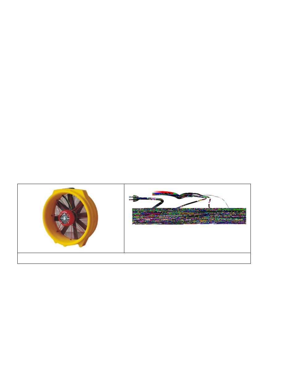
Figure 15: Model 2350 fan and Fan Top.
To connect the 2350 to the DM-2 Digital Pressure Gauge
1. Set the fan speed control knob as low as it will go (counter clock-wise), and power switch in the off position.
2. Connect the power cord from the fan to a compatible wall outlet.
3. Connect a pressure tube from the “Ref B” (yellow) port on the Fan Top to the “Ref B” (yellow) port on the
DM-2.
4. Connect the Speed Control Cable from the DM-2 “Speed Control” port to a Control Port on the fan.
5. Connect another 2350 fan by connecting a standard Ethernet-style cable from a Control Port of one fan to a
Control Port on the second.