Check motor and fan blade position, Check for flow sensor leaks, Perform a field verification monthly – Retrotec Blower Door User Manual
Page 50: Maintain system for optimum operation
Page 50 of 87
©Retrotec Inc. 2015
6. Maintain system for optimum operation
Regular ongoing maintenance is an important part of keeping equipment in a usable condition.
Before performing a test, the pressure connections on the fan must be inspected for blockages that can occur due to
water or dust. Allowing excessive quantities of gypsum dust to enter the fan will prematurely wear out the bearings and
may plug the fan pressure ports, preventing the measurement of pressures and flows. If dust is observed, or the fan has
been in an environment high in dust or moisture, use a vacuum cleaner to clear the 4 ports on the fan nacelle of dust
and/or water in the places where the tubing attaches to the fan. The nacelle is the housing is mounted upstream from
the motor.
Retrotec Door Fans maintain their calibration unless physical damage occurs. Conditions which could cause the fan
calibration to change are movement of the motor and blades, relative to the fan housing, damaged flow sensors, and
leaks in the sensor or tubing running from the flow sensor to the fan pressure tap.
6.1
Check motor and fan blade position
Fan calibration can change if there has been movement of the motor and blades, relative to the fan housing. Such a
damaged condition will be easily apparent if the C8 Range Plate will not sit properly on Range Ring B, or if the motor
mount looks bent.
6.2
Check for Flow Sensor leaks
Retrotec calibrated fans use four flow sensors that are mounted inside the plastic housing that goes over the front of
the fan.
To test for leaks in the sensor or from the sensor to the fan pressure tap
1. Attach a piece of tubing to the yellow connector on top of the fan.
Leave the other end of the tubing open.
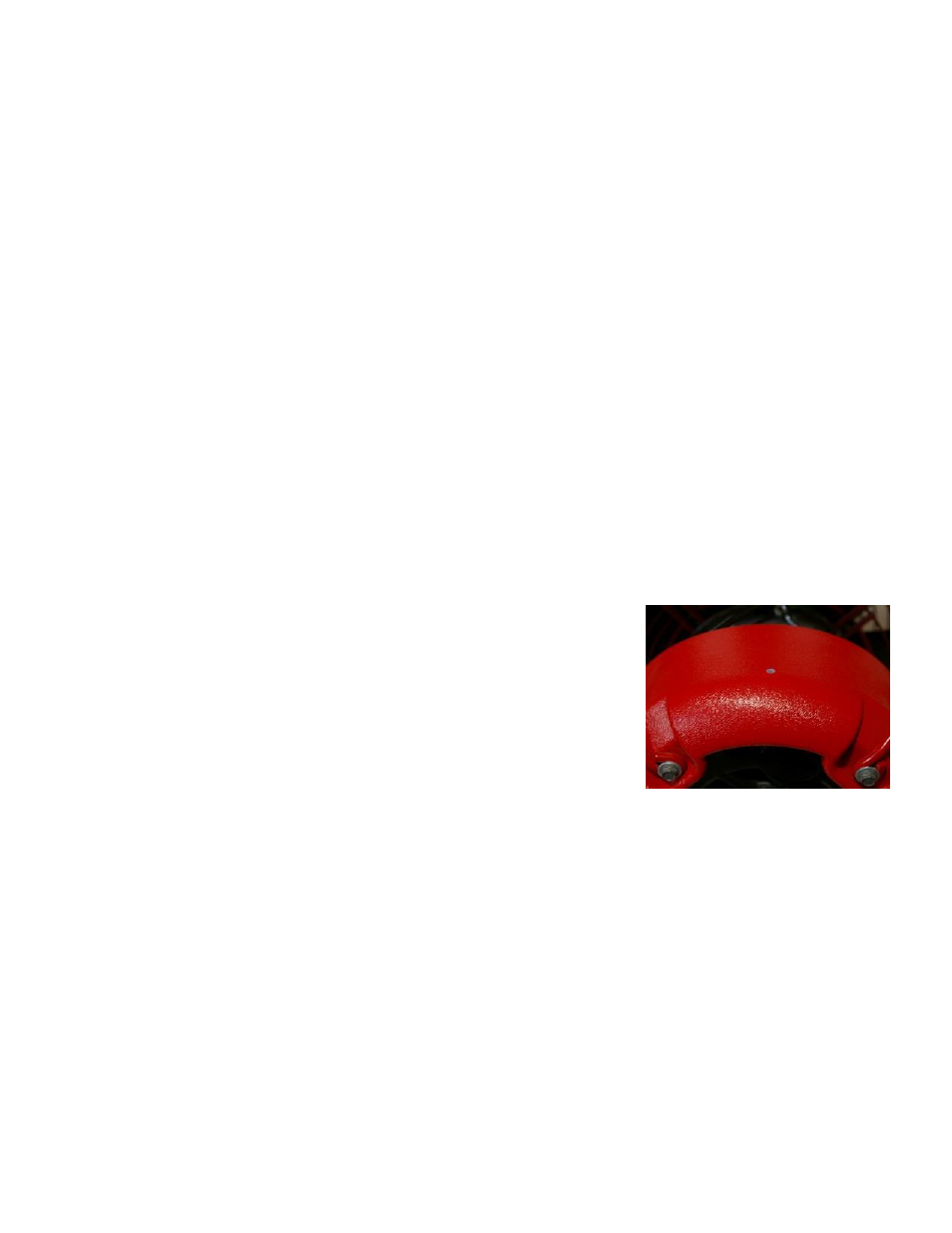
2. Find the four small holes located on the red plastic that covers the
motor. They should be evenly spaced around the motor, with one on
the top, bottom, left, and right. Temporarily seal the four holes by
covering them with masking tape.
3. Suck on the open end of the tube, to create a vacuum in the tubing.
Cover the end of the tube with your tongue or finger, if the tubing
sticks, a vacuum has been created, and the flow sensor does not leak.
Make sure that the vacuum persists for at least 5 seconds. If you
hear a sound of air moving through the tubing, then there may be a
disconnection inside the fan somewhere.
4. Remove the tape from each hole individually, and ensure that air can be sucked through that particular hole.
Check each of the four pressure sensing points in turn.
6.3
Perform a field verification monthly
A field verification of the fan calibration should be performed approximately monthly. It is a simple way to verify
that the equipment is still operating correctly. Some standards such as RESNET require this to be done yearly and
for records to be kept. This “check” is not a calibration of any range in particular but does test the pressure pickups
to see if they are leaking or blocked because those are the most common problems with the equipment. If one
range is reading correctly, there is a good chance the others are also but this does not take the place of a complete
Figure 31: Pressure sensor on the fan motor
casing.