Subaru Robin SGX3500 User Manual
Page 41
- 39 -
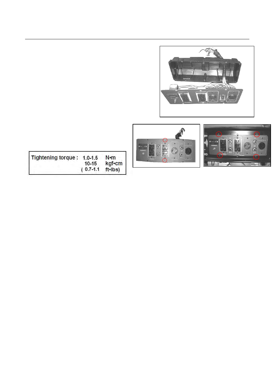
7-4-8 CONTROL BOX ASSY
(1) Pass wires drawn out generator and engine
to the control box.
(2) Connect the wires coming from the control
panel with wires coming from generator and
engine.
NOTE : Connect the wires of the same color.
(3) Mount the control panel together with the
control box (Control box Assembly) onto the frame.
M4 × 12 mm flange bolt . . . 2 pcs.
(4) Install the control box onto the frame.
M4 × 12 mm flange bolt . . . 4 pcs.
7-5 CHECKING, DISASSEMBLY and REASSEMBLY of the CONTROL PANEL
7-5-1 CHECKING OF THE CONTROL PANEL
Dismount the control box assy. from frame. Remove the control box from control panel and check
each components and wiring. Refer to Section 6 for the detail of checking procedure for the
components in the front panel.
7-5-2 DISASSEMBLY
(1)
Remove the end cover and disconnect the wires to the control panel.
(2)
Remove the control box from the frame and remove the control panel.
(3) After disconnecting individual wires, remove the control panel components.
7-5-3 REASSEMBLY
(1) Install the receptacles, circuit breakers, terminals, switches, etc. on the control panel and wire
them.
NOTE : Circuit diagrams are shown in Section 9. Colored wires are used for easy identification,
and are of the correct capacity and size. Use heat-resistant type wires (permissible
temperature range 75°C or over) in the specified gauge shown in the circuit diagrams.
(2) Connect the wires of control panel components.
(3) Attach the control panel and control box to the frame.
(Refer to 7-4-9 for details.)