Thermo Pride Premiere XT 16 SEER User Manual
Page 15
15
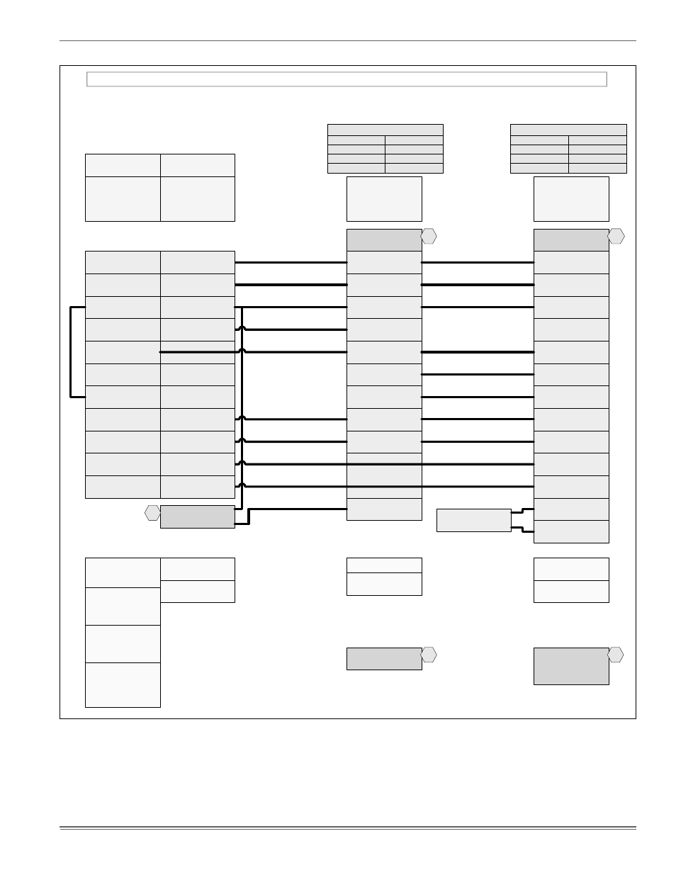
FIGURE 16: Thermostat Wiring – Two-Stage Heat Pumps - Two-Stage Variable Speed Furnaces
HP 24C
Two Stage Heat Pump – Two Stage Variable Speed Furnace (With Hot Heat Pump Operation)
O
Reversing Valve
Energized in Cool
C
24 – Volt Common
R
24 – Volt Hot
W1 OUT
First Stage Heat
W2 OUT
Second Stage Heat
Y2 OUT
Second Stage Compressor
Y1
Single Stage Compressor
X/L
Malfunction Light
Y2
Second Stage Compressor
W
Auxiliary Heat
BS
Bonnet Sensor
BSG
Bonnet Sensor
TWO STAGE
HEAT PUMP
Bonnet Sensor
(Optional)
Change FFuel jumper
on the heat pump control
to “ON”
Part Numbers:
SAP = Legacy
126768 = 031-09137
18395 = 031-01996
340512 = 031-09178
1
1
Part Numbers:
SAP = Legacy
265904 = 031-09169
2
C
24 – Volt Common
R
24 – Volt Hot
Y1
Single Stage Compressor
TWO STAGE
VARIABLE SPEED
FURNACE CONTROL
G
Fan
TWO STAGE
VARIABLE SPEED
FURNACE
W/W1
First Stage Heat
Y/Y2
Second or Full
Stage Compressor
W2
Second Stage Heat
O
Reversing Valve
X/L
Malfunction Light
DHUM
Dehumidification
2
Move HEAT PUMP
jumper to “YES”
Move DHUM
jumper to “YES”
if humidistat is to be used.
PV(8/9)
ID MODELS
(F/L)*(8/9)V
YORKGUARD VI
CONTROL
(G/L)(8/9)V
YZE
OD MODELS
YZH
H*5
H*8
C
24 – Volt Common
R
24 – Volt Hot
Y1
First Stage Compressor
O
Reversing Valve
Energized in Cool
L
Malfunction Light
Y2
Second Stage Compressor
G
Fan
*DN22H00124
*DP22U70124
THERMOSTAT
E/W1
First Stage Aux. Heat
W2
Second Stage Aux. Heat
C
24 – Volt Common
Y
First Stage Compressor
O/B
Reversing Valve
L
Malfunction Light
Y2
Second Stage Compressor
G
Fan
*PP32U70124
THERMOSTAT
E
Emergency Heat
R
24 – Volt Hot
(Heat XFMR)
RC
24 – Volt Hot
(Cool XFMR)
AUX
Auxiliary Heat
Step 1 of Thermostat
Installer/Configuration
Menu must be set to “HP2”
Selection of GAS/ELEC
switch on thermostat
not necessary
Thermostat Installer Setup
0170-System Type-
must be set to 12
3 Heat/2 Heat Pump
Thermostat Installer Setup
0190-Changeover Valve-
must be set to 0
O/B terminal
Energized in Cooling
Thermostat Installer Setup
0200-Backup Heat Source-
must be set to 1
Heat Pump Backup Heat
Source is Fossil Fuel
External Humidistat
(Optional)
Open on Humidity Rise
Thermostat Installer Setup
0210-External Fossil Fuel
Kit- must be set to 1
Heat Pump Control
is Controlling Heat Pump
Backup Heat
Change Hot Heat Pump
jumper on the heat pump
control to “ON”
3