Notice – Thermo Pride Premiere XT 16 SEER User Manual
Page 7
7
SECTION VIII: ELECTRICAL
CONNECTIONS
GENERAL INFORMATION & GROUNDING
Check the electrical supply to be sure that it meets the values specified
on the unit nameplate and wiring label.
Power wiring, control (low voltage) wiring, disconnect switches and over
current protection must be supplied by the installer. Wire size should be
sized per NEC requirements.
The complete connection diagram and schematic wiring label is located
on the inside surface of the unit service access panel and this instruc-
tion.
FIELD CONNECTIONS POWER WIRING
1. Install the proper size weatherproof disconnect switch outdoors and
within sight of the unit.
2. Remove the screws at the bottom of the corner cover. Slide corner
cover down and remove from unit. See Figure 6.
3. Run power wiring from the disconnect switch to the unit.
4. Remove the service access panel to gain access to the unit wiring.
Route wires from disconnect through power wiring opening provided
and into the unit control box.
5. Install the proper size time-delay fuses or circuit breaker, and make
the power supply connections.
6. Energize the crankcase heater if equipped to save time by preheat-
ing the compressor oil while the remaining installation is completed.
FIELD CONNECTIONS CONTROL WIRING -
CONVENTIONAL
1. Route low voltage wiring into bottom of control box as shown in Fig-
ure 6. Make low voltage wiring connections inside the junction box
per Figures 10 - 15.
2. The complete connection diagram and schematic wiring label is
located on the inside surface of the unit service access panel.
3. Replace the corner cover and service access panel removed in
Steps 2 and 4 of the “Field Connections Power Wiring” section.
4. All field wiring to be in accordance with national electrical codes
(NEC) and/or local-city codes.
5. Mount the thermostat about 5 ft. above the floor, where it will be
exposed to normal room air circulation. Do not place it on an outside
wall or where it is exposed to the radiant effect from exposed glass
or appliances, drafts from outside doors or supply air grilles.
6. Route the 24-volt control wiring (NEC Class 2) from the outdoor unit
to the indoor unit and thermostat.
FIELD CONNECTIONS CONTROL WIRING -
COMMUNICATING
1. The Communication Harness is provided with the communicating
thermostat.
2. Route low voltage four conductor shielded thermostat communica-
tions harness into junction box and connect to communications port
on control board. See Figure 6.
3. The complete connection diagram and schematic wiring label is
located on the inside surface of the unit service access panel.
All field wiring must USE COPPER CONDUCTORS ONLY and be in
accordance with Local, National Fire, Safety & Electrical Codes. This
unit must be grounded with a separate ground wire in accordance
with the above codes.
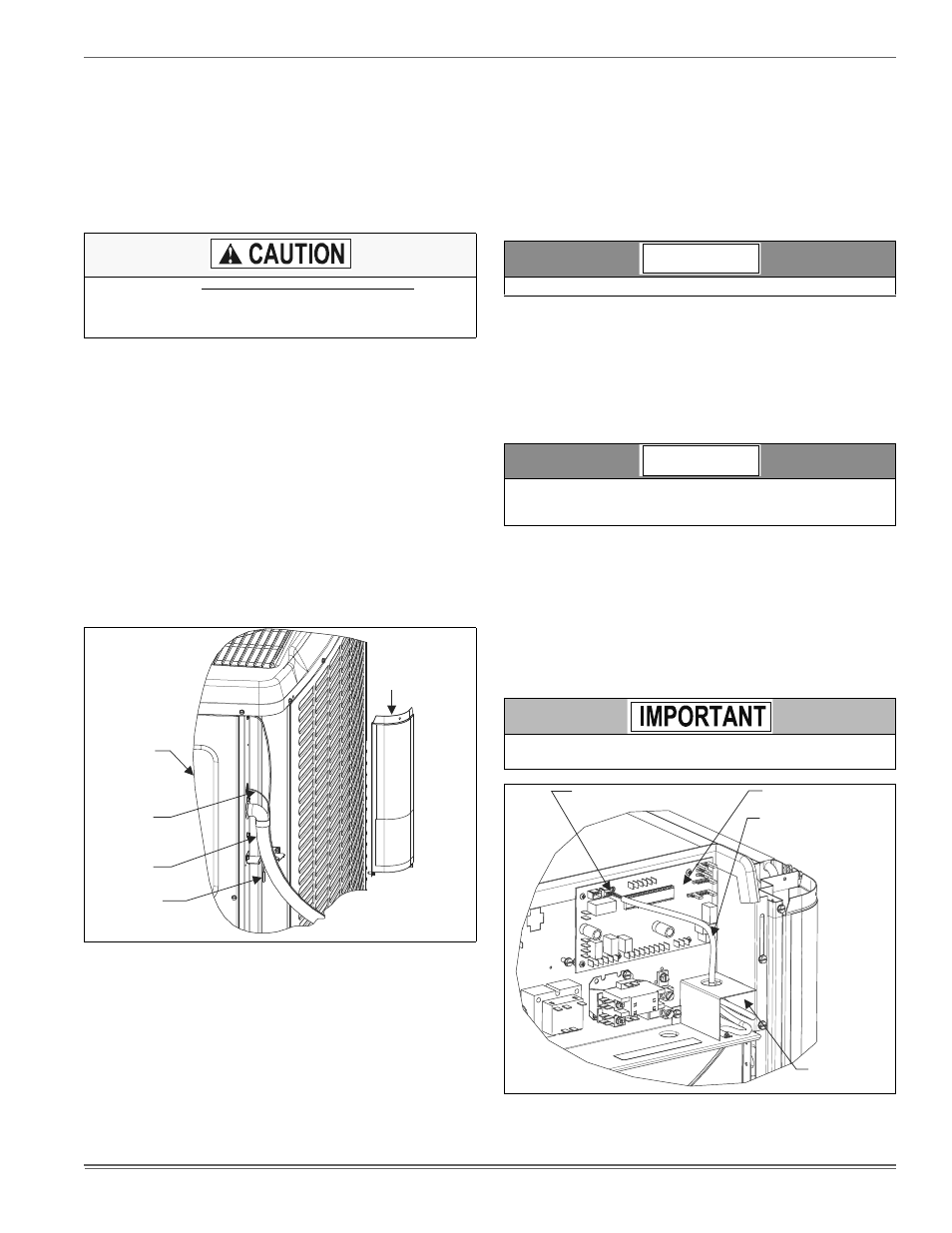
FIGURE 6: Typical Field Wiring
Corner
Cover
Control
Wiring
Power
Wiring
Service
Access
Panel
Ambient
Temperature
Sensor
Ambient temperature sensor should extend below corner cover by 1”.
To eliminate erratic operation, seal the hole in the wall at the thermo-
stat with permagum or equivalent to prevent air drafts affecting the
operation of in the thermostat.
If unit is going to be setup as a communicating system, the conven-
tional wiring must be removed from the Outdoor Control Board.
FIGURE 7: Communications Harness Connection
NOTICE
NOTICE
COMMUNICATIONS PORT
CONTROL BOARD
COMMUNICATIONS
HARNESS
JUNCTION
BOX