SAF-HOLLAND XL-PH10412UM PH-995 Pin and Clevis Coupler User Manual
Page 8
8
XL-PH10412UM-en-US Rev A · 2011-10-28 · Amendments and errors reserved. © SAF-HOLLAND, Inc.
Mounting Instructions
5. PH-995SH71 – Complete
Assembly Installation
Before installation make sure that the
mounting structure is of sufficient strength
to support the rated capacities of the
coupler. Refer to SAE J847 for structural
performance requirements.
NOTE: Due to weight of the complete
assembly, lifting and installing
may require two installers.
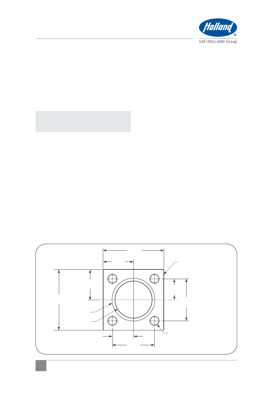
1. Install the housing flange to a flat
mounting surface using the bolt hole
pattern as specified (Figure 3).
Figure 3
.28"(7.1 mm)
X 45º CHAMFER
Ø 4.00"
(101.6 mm)
2.25"
(57.2 mm)
Ø .94"
(23.9 mm)
MIN. CLEARANCE AREA
4.50"
(114.3 mm)
6.50"
(165.1 mm)
3.25"
(82.6 mm)
3.25"
(82.6 mm)
6.50"
(165.1 mm)
2.25"
(57.2 mm)
4.50"
(114.3 mm)