Scsi interrupt enable zero (sien0), Scsi interrupt enable zero, Sien0) – Avago Technologies LSI53C895A User Manual
Page 182: Registers: 0x3c–0x3f, Register: 0x40
4-74
Registers
When the COM bit is set, the ID is stored only in the
SSID register, protecting the SFBR from being
overwritten if a selection/reselection occurs during a DMA
register-to-register operation.
Registers: 0x3C–0x3F
Adder Sum Output (ADDER)
Read Only
ADDER
Adder Sum Output
[31:0]
This register contains the output of the internal adder,
and is used primarily for test purposes. The power-up
value for this register is indeterminate. It is used to
determine if the correct memory address was calculated
for a relative jump SCRIPTS instruction.
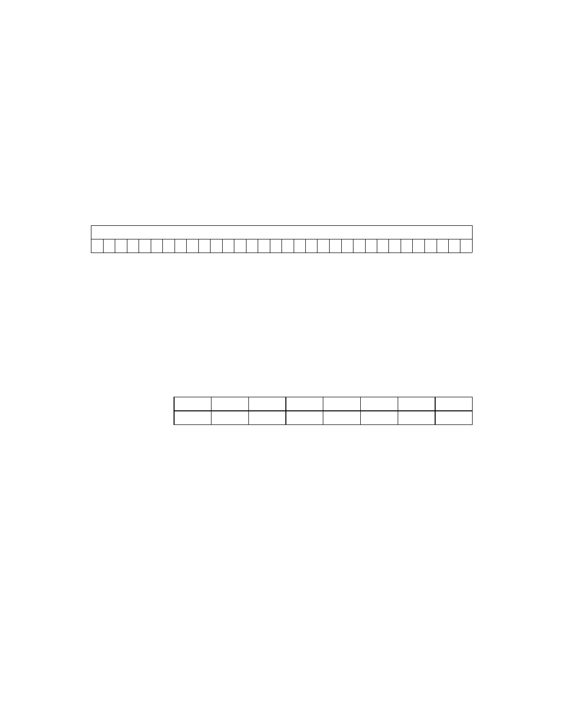
Register: 0x40
SCSI Interrupt Enable Zero (SIEN0)
Read/Write
This register contains the interrupt mask bits corresponding to the
interrupting conditions described in the
register. An interrupt is masked by clearing the appropriate mask
bit. For more information on interrupts, see
M/A
SCSI Phase Mismatch - Initiator Mode;
7
SCSI ATN Condition - Target Mode
In the initiator mode, this bit is set when the SCSI phase
asserted by the target and sampled during SREQ/ does
not match the expected phase in the
register. This expected phase is
automatically written by SCSI SCRIPTS. In target mode,
this bit is set when the initiator asserts SATN/. See the
31
0
ADDER
x
x
x
x
x
x
x
x
x
x
x
x
x
x
x
x
x
x
x
x
x
x
x
x
x
x
x
x
x
x
x
x
7
6
5
4
3
2
1
0
M/A
CMP
SEL
RSL
SGE
UDC
RST
PAR
0
0
0
0
0
0
0
0