Remote control, Vca level control, Trigger logic inputs – Ashly mXa-1502 12-Channel 4-Zone DSP Mixer-Amplifier User Manual
Page 32: Gpo logic outputs, Amp fault logic outputs, Remote standby, Ashly remotes, Wr-1.0 and wr-1.1, Use the ashly, Wr-1
7
Remote Control
7.1
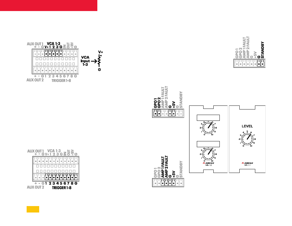
VCA Level Control Inputs
Remote DC level control is available on these
three VCA (voltage controlled amplifier)
inputs. A VCA Gain block is first placed in any
input or output signal chain, then assigned to
a VCA input. Multiple VCA gain blocks can be
assigned to the same VCA input pin.
Ashly WR-1, WR-1.1, or WR-1.5 remotes can be
used for DC level control, or a custom control
can be made using a 10k Ohm potentiometer
and wired as shown. The dot indicates the
potentiometer clockwise position, full volume.
7.2
Trigger Logic Inputs
Eight programmable trigger inputs are
available for use with contact closure switches.
Triggered events are programmed in the
software Events screen, [Events>Triggered
Events> New event].
Triggered events include: A/B Source Select,
Action Sequence, Channel Mute, GPO Logic
Toggle, Mixer Mute, Paging, Pause/Resume
Schedules, Power On/Standby, and Preset
Toggle. Connecting a trigger input to the [G]
pin (ground) triggers the event.
Current trigger status can be viewed in the
[Settings>Panels>Rear Panel] screen.
7.3
GPO Logic Outputs
Two GPO (general
purpose output) pins
are available for driving
external device logic
inputs to effect a lighting
change, motorized
curtain, projector screen,
etc. GPO logic status can
be toggled as part of a
preset, or can be toggled
from a scheduled or triggered event.
Current logic High or Low status is viewed or set
in the [Settings>Panels>Rear Panel] screen.
7.4
Amp Fault Logic Outputs
An amplifier fault is any
condition that places the
amplifier into a protect
state. Faults can include
output overcurrent,
thermal, mains over-
voltage, internal mains
fuse, and output DC. If an
amplifier channel goes
into protect mode, the amp fault output pin for
that channel goes logic low.
7.5
Remote Standby
Standby mode puts the amplifier into a reduce
power state. Standby mode can be activated
via software, scheduled
or triggered events, or
with the standby pin
Euroblock connection.
Standby pin polarity
can be set in software
to Trigger on Low
or Trigger on High
[Settings>Panels>Rear Panel].
The Standby contact closure always has
priority over software or event driven standby.
7.6
Ashly Remotes
WR-1.0 and WR-1.1
The WR-1 and WR-1.1 are remote level
controllers used for DC level control inputs.
The WR-1.0 (dual potentiometer) and WR-1.1
(single potentiometer) mount to a standard
North America electrical wall box. The remote is
32
mXa-1502 • Operating Manual