Status leds, Power switch, Bridge led – Ashly mXa-1502 12-Channel 4-Zone DSP Mixer-Amplifier User Manual
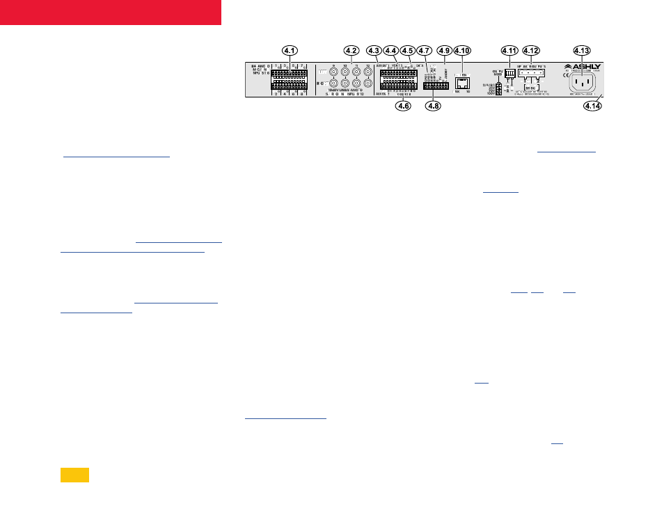
Page 7: Rear panel features, Mic/line inputs, Stereo line inputs, Aux out 1 & 2, Vca 1-3 input, Data connection, Trigger 1-8 input
3.6
Status LEDs
Com
LED indicates Ethernet activity.
Protect
LED indicates the amplifier has
encountered a fault condition and has shut
down its power supply.
Sleep
LED turns on when the amplifier is in
sleep mode, as configured in software. To set
sleep mode on/off and set the audio inactivity
time before the amplifier goes to sleep, go to
The
Disable
LED is lit when the power switch
has been disabled from software.
3.7
Power Switch
The power switch turns the unit on or off, and
also flashes when in standby. The power switch
can be disabled in software. To disable the
power switch, go to [
Panel>Enable Front Panel Power Button
3.8
Bridge LED
This green LED indicates the amplifier has been
set to BRIDGE mode from software. To select
Bridge mode, go to [
].
4
Rear Panel Features
4.1
Balanced Mic/Line Inputs
This is used for a three wire (G, +, -) balanced
analog input using 3.5mm Euroblock
connectors. If an unbalanced input signal is to
be connected here, wire the hot signal to (+),
the input ground to (G), and connect the (-) pin
to (G). Maximum input level is +21dBu.
4.2
-10dBV Unbalanced Stereo Line
Inputs
These RCA jacks are used for stereo line level
inputs (-10dBv). Note: Unbalanced line level
sources may reference their outputs to a
different ground than this amplifier, creating
the potential for ground loop hum. Always use
short cable lengths for unbalanced signals,
routed away from AC, video, or data cables, and
make every effort to use a common grounding
point for all devices. In the event there is still
ground loop hum, isolate the unbalanced input
signal by using an in-line isolation transformer.
4.3
AUX Out 1 & 2
AUX outputs offer additional and independent
post-DSP signals for driving other amplifiers or
processors. AUX outputs are configured in the
section. AUX outputs use
balanced signals.
4.4
VCA 1-3
A VCA (voltage controlled amplifier) is used to
remotely control one or more
placed in the software signal chain. Ashly WR-
1, WR-1.1, and WR-1.5 remotes can be wired
to VCA 1-3 input pins to control the assigned
for example.
4.5
Data
These four pins offer serial data control for
future remote control development.
4.6
Trigger 1-8
Eight contact closure pins can be used
for triggering mXa-1502 events or event
sequences that have been programmed in
software. See section
for
details and available event action types.
4.7
GPO 1 & 2
These two pins provide logic outputs that are
referenced to the closest ground (G) and +5V
pins on the same connector. Logic outputs are
generated from presets or amplifier events,
and can be assigned high or low in software.
See section
for example.
4.8
Amp 1 & 2 Fault
Fault output pins are logic-high (+3V) when
the amp channel is on and ok, but transition to
logic-low (0V) when the amp channel is off or in
a protect/fault state. See section
for details.
7
mXa-1502 • Operating Manual