Diodes AP3988/89/90 User Manual
Page 8
AP3988/89/90
Document number: DS36722 Rev. 3 - 2
8 of 13
www.diodes.com
March 2014
© Diodes Incorporated
AP3988/89/90
A Product Line of
Diodes Incorporated
N
E
W
P
R
O
D
U
C
T
Operation Description
(Cont.)
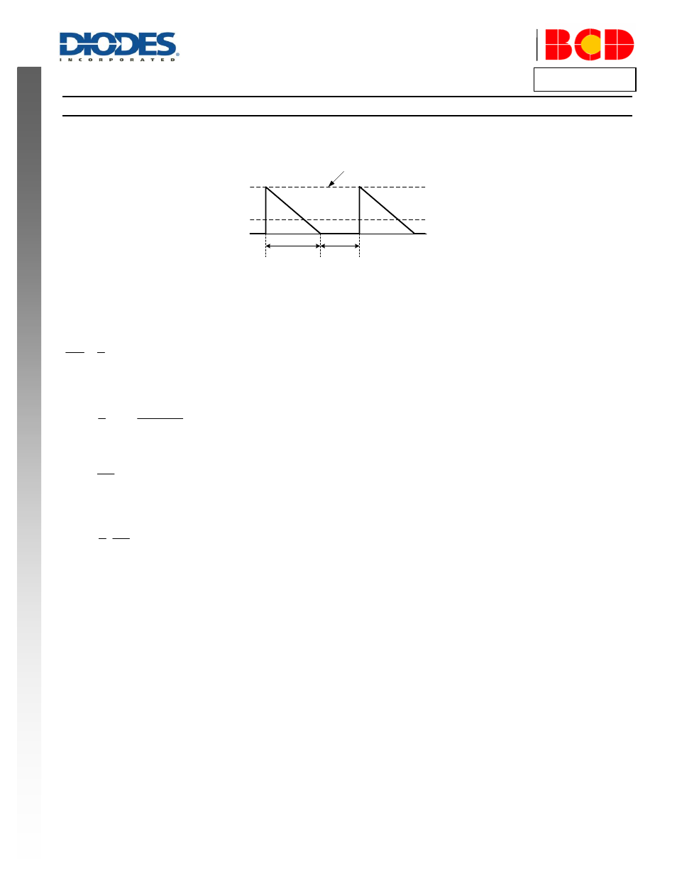
Constant Current Operation
The AP3988/89/90 is designed to work in constant current (CC) mode. Figure 4 shows the secondary current waveforms.
I
s
0A
See equation 7
T
ons
T
offs
I
OUT
Figure 4. Secondary Current Waveform
In CC operation, the CC loop control function of AP3988/89/90 will keep a fixed proportion between D1 on-time T
ons
and D1 off-time T
offs
by
discharging or charging the built-in capacitance connected. This fixed proportion is
3
4
offs
ons
T
T
………
(6)
The relation between the output constant-current and secondary peak current I
PKS
is given by:
offs
ons
ons
PKS
OUT
T
T
T
I
I
2
1
………
(7)
At the instant of D1 turn-on, the primary current transfers to the secondary at an amplitude of:
PK
S
P
PKS
I
N
N
I
………
(8)
Thus the output constant current is given by:
PK
S
P
OUT
I
N
N
I
7
2
………
(9)
Leading Edge Blanking (LEB)
When the power switch is turned on, a turn-on spike on the output pulse rising edge will occur on the sense-resistor. To avoid false termination of
the switching pulse, a typical 500ns leading edge blanking is built in. During this blanking period, the current sense comparator is disabled and the
gate driver cannot be switched off.
The built-in LEB in AP3988/89/90 has shorter delay time from current sense terminal to output pulse than those IC solutions adopting external RC
filter as LEB.
Built-in Cable Compensation
The AP3988/89/90 has built-in fixed voltage of 0.35V typical to compensate the drop of output cable when the load is changed from zero to full
load. A typical 10nF external capacitor connected to the CPC pin is used to smooth voltage signal for cable compensation.
Over Temperature Protection
The AP3988/89/90 has internal thermal sensing circuit to shut down the PFM driver output when the die temperature reaches 160°C typical. When
the die temperature drops about 40°C, the IC will recover automatically to normal operation.