Leds (d1 through d8), Leds (d1 through d8) -18 – Altera Stratix II GX EP2SGX90 Transceiver Signal Integrity Development Board User Manual
Page 28
Advertising
2–18
Reference Manual
Altera Corporation
Stratix II GX EP2SGX90 Transceiver Signal Integrity Development Board
May 2006
Interfaces
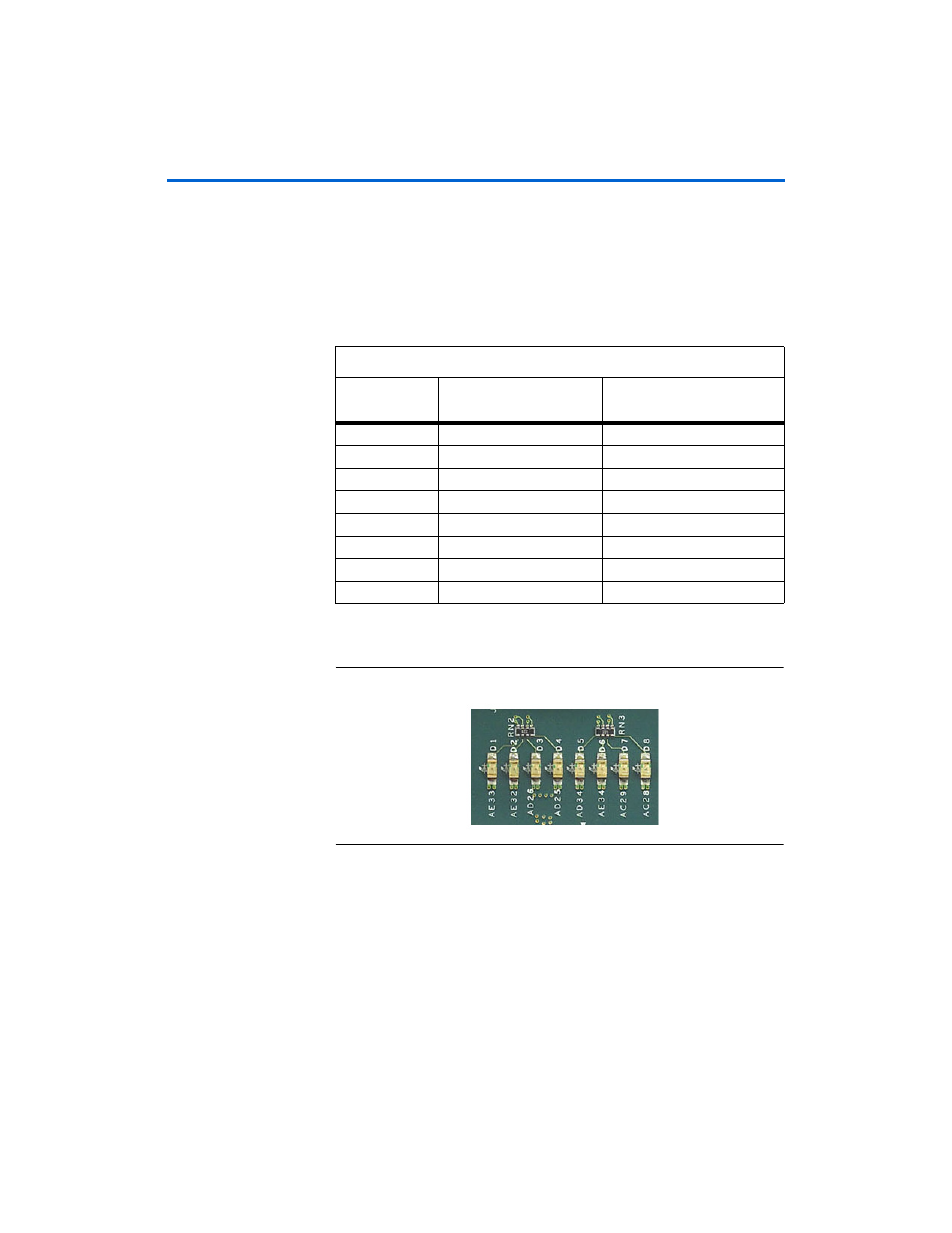
LEDs (D1 Through D8)
The board provides eight user-defined LEDs. D1 through D8 are
connected to general purpose I/O pins on the Stratix II GX EPS2GX90
device. When the EP2SGX90 device drives logic 0, the corresponding LED
illuminates.
lists the schematic signal name and the
corresponding Stratix II GX device’s pin number.
shows a board image of the user-defined LEDs.
Figure 2–10. User-Defined LEDs
Table 2–11. User-Defined LED Pin-Out
Board
Reference
Schematic Signal Name
Stratix II GX (U20)
Pin Number
D1
USER_LED0
AE33
D2
USER_LED1
AE32
D3
USER_LED2
AD26
D4
USER_LED3
AD25
D5
USER_LED4
AD34
D6
USER_LED5
AE34
D7
USER_LED6
AC29
D8
USER_LED7
AC28
Advertising