MIPRO act707d(2ce150)b User Manual
Page 4
4
5
(Fig.3)
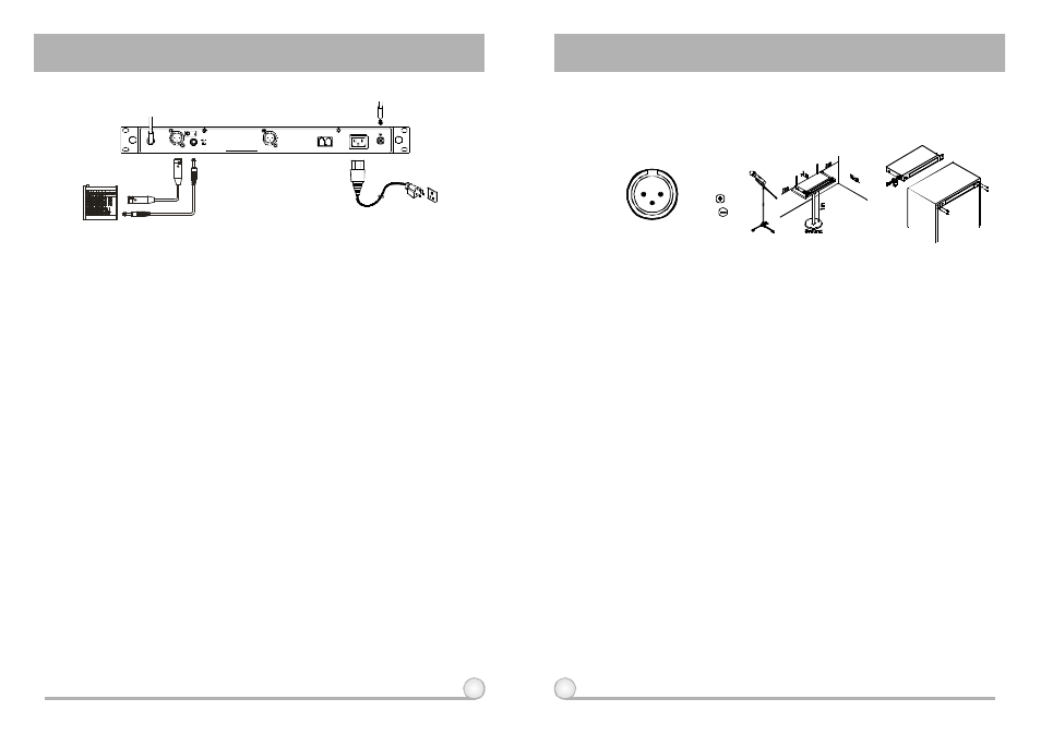
3. INSTALLATION OF THE RECEIVER
1.
Install 2 separate antennas o n the antenna sockets (6), (13) o n the rear
panel. Illustrated in
2.
PowerOutput Connection:
Fig. 3.
(a) Unbalanced Level Switch (9) Setting Position: When inputs the unbalanced
output of a receiver into "AUX-IN" input jack of a mixer or amplifier or "Electric
Guitar", switch the Level Switch (9) to the right "LINE" position. Low
sensitivity may occur if switch to the wrong position. When input the
unbalanced output of a receiver into the "MIC-IN" input jack of a mixer or
amplifier; switch the Level Switch (9) to the left "MIC" position. Over load
distortion may occur if switch to the wrong position. When using electric guitar,
don't use "MIC" position as it may have generated insufficient level.
(b) Unbalanced Output: Using audio output cable attached with "PHONE PLUG"
type, connect one end from the unbalanced output jack (8) of the receiver,
and the other end to the "LINE-IN" input jack of the amplifier, as shown in Fig.
3.
(c) Balanced Output: Using audio output cables attached with "XLR" or "Cannon"
type, connect one end from the balanced output jacks (7) of the receiver, and
the other end to the "MIC IN" input jack of the mixer or amplifier, as shown in
Fig. 3. (The characteristic of the 3-pin connector is as shown in Fig. 4
(d) Guitar Output: Using audio output cable attached with "PHONE PLUG" type,
plug one end from the unbalanced output jack of a receiver, and the other
end to the input jack of a guitar amplifier. Switch the Level Switch (9) to
"LINE" position.
(d) Guitar Output: Using audio output cable attached with "PHONE PLUG" type,
plug one end from the unbalanced output jack of a receiver, and the other
end to the input jack of a guitar amplifier. Switch the Level Switch (9) to
"LINE" position.
(Fig.4)
3.
Audio Output Connection:
(a) With the appropriate AC power cable connects from AC Input Jack (12) to an
AC outlet under the marked voltage 85~265 V, as shown in Fig. 5.
3: COLD
1:GND
2:HOT
3
2
1
(Fig.6)
(Fig.5)
4.
To ensure best reception possible, receiver must be installed at least one
meter above ground. In addition, the distance between transmitter and
receiver must be more than one meter and away from noise. (Shows in
)
Fig. 5.
5.
With rackmount kit, receiver can be inststalled on the standard 19-inch
rackcase. (Shows in Fig. 6.)
One can also purchase front antenna
converting kits from your local dealer. When installing front antenna
converting kits, remove plugs from 4 pre-drilled openings. Then, install
the antenna base o f the converting cable on the pre-drilled opening for
antenna. Finally, install antennas directly to the antenna bases to
increase receiving efficiency of antennas.
ACT DUAL CHANNEL WIRELESS RECEIVER
ACT DUAL CHANNEL WIRELESS RECEIVER
3 : C O L D
-
1 : G N D
+
2 : H O T
3
2
1
MADEINTAIWAN
LEVEL
MIXOUT
B A L A N C E D O U T B
ANTENNAA
AC100V~240V
MIC
LINE
+8VDCBIAS
+8VDCBIAS
ANTENNAB
REMOTE
I N
OUT
B A L A N C E D O U T A