MIPRO act707d(2ce150)b User Manual
Page 9
ACT DUAL CHANNEL WIRELESS RECEIVER
ACT DUAL CHANNEL WIRELESS RECEIVER
6. COMPUTER NETWORK INTERFACE OPERATION
1.
Except for receiver module, both receiver with L C D display h a v e t h e most
advance function ofcomputer-network-interfaced controlling system.
2.
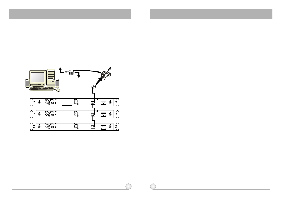
Wiring Instruction
②
③
Please connect one end of the phone cable (included) to remote connector's
"OUT" jack (11) on the back of the first receiver and connect the other end of
cable to remote connector's "IN" jack (11) on the back of second receiver.
(Shows in Fig 7.) Continue such parallel connection with remaining receivers.
Once all receivers are parallels connected, connect a phone cable from
remote connector's "IN" jack (11) on the back of first receiver to MIPRO-DV
converter.
This interface system adapts parallel connection. Therefore, it takes only 2
linking wires to complete the connection to the converter of the whole system.
① Connect the network interface remote connector (11) on the back of the
receiver to the interface converter (requires at least 2 linking cables for each
pairing). Then, use RS-232 cable connects the converter to the RS-232 COM
PORT on the computer.
(Fig.7)
④
⑤
This system can connect up to 64 receiver for simultaneous operation.
Though longer the distance is, worse the stability will be; nevertheless, the
network connecting cable can still operate while it is 300 meters long.
However, it is our recommendation to keep the cable under 100 meters long
to ensure high-speed transmission.
7. CAUTIONS
1.
When using DC power supply, please be aware of the operating voltage.
First of all,please make sure minimum of 12 volts can be obtained for
function properly. However, the power supply should not exceed its
maximum capacity of 15 volts. When the supply voltage is more than 15
volts, the system will suffer severe internaldamage. It is preferred the
power source is from a regulated power with the minimum current of 1 A.
2.
Use only MIPRO standard antenna to ensure the sensitivity o f t h e
receiver.
3.
Antenna socket has 8-volts DCpower supply; please do not short the
circuit of this part.
1 4
15
CONVERTER
TO P C R S - 2 3 2 C O M PORT
TOPCKEYBOARDCONNECTOR
TOKEYBOARD CONNECTOR
3:COLD -
1:GND
+
2:HOT
3
2
1
MADEINTAIWAN
LEVEL
M I X O U T
B A L A N C E D O U T B
ANTENNAA
AC100V~240V
M I C
LINE
ANTENNAB
REMOTE
IN
OUT
B A L A N C E D O U T A
+ 8 V D C B I A S
+8VDCBIAS
RX1
RX2
R X 3
PC
3:COLD -
1:GND
+
2:HOT
3
2
1
MADEINTAIWAN
LEVEL
M I X O U T
B A L A N C E D O U T B
ANTENNAA
AC100V~240V
M I C
LINE
ANTENNAB
REMOTE
IN
OUT
B A L A N C E D O U T A
+ 8 V D C B I A S
+8VDCBIAS
3:COLD -
1:GND
+
2:HOT
3
2
1
MADEINTAIWAN
LEVEL
M I X O U T
B A L A N C E D O U T B
ANTENNAA
AC100V~240V
M I C
LINE
ANTENNAB
REMOTE
IN
OUT
B A L A N C E D O U T A
+ 8 V D C B I A S
+8VDCBIAS