Wiring the encoder, Testing the encoder – Applied Motion 3540i User Manual
Page 14
Page 4 of 4
+5V +CH1- +CH1- GND
single
ended
encoder
+5V
A
B
GND
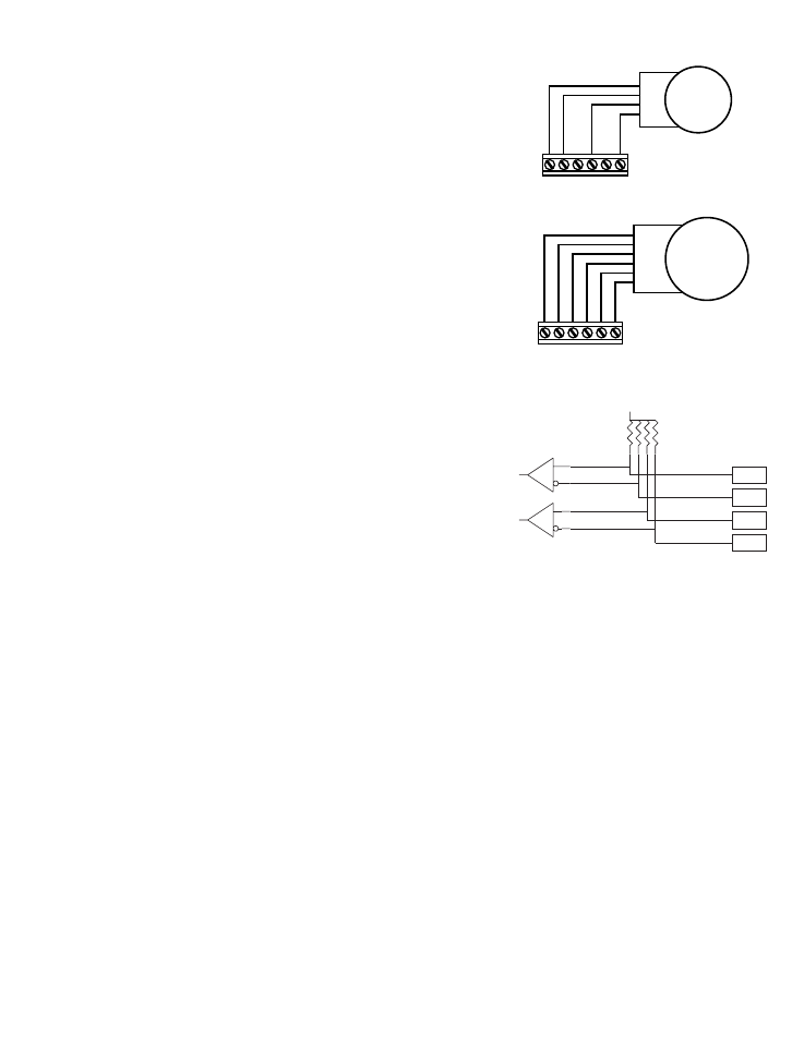
Connecting a Single Ended Encoder
Connecting a Differential Encoder
Encoder Board Schematic
+5V +CH1- +CH1- GND
differential
output
encoder
+5V
A+
A-
B+
B-
GND
Wiring the Encoder
The 1000-175 option board is designed for use with single ended or
differential output quadrature encoders. Differential encoders are
recommended because they provide better noise immunity.
There is one restriction on your choice of encoder. The motor resolution must
be a multiple of the encoder resolution. Keep in mind that the drive uses "X4"
decoding of the encoder signals, so a 1000 line encoder produces 4000
counts per revolution.
An excellent choice of encoders is the U.S. Digital E2-1000 series. That unit
has a 1000 line code wheel, which produces 4000 counts/rev at the drive.
That will work well with a motor resolution of 20000 step/rev, which is the
default setting. Simply set the encoder ratio (ER software command) at 5.
The U.S. Digital E2-500 series is also popular and provides 2000 counts/rev.
For the E2-500, set ER at 10.
The sketches on the right show proper wiring for single ended and differential
encoders. Built-in "pull up" resistors are provided for "open collector" encoder
outputs. A +5VDC output is provided for powering the encoder. 100 mA is
available.
The schematic diagram of the encoder input circuitry is shown at the right.
+5VDC
DS26C32
DS26C32
CH1+
CH1-
CH2+
CH2-
10K
Testing the Encoder
In the diagram above, we suggested that you connect the encoder A
channel to the drive's CH1 input, and the encoder B channel to CH2.
However, depending on how your motor is wired, this might cause the
encoder to count in the opposite direction as the motor. That's bad,
because encoder position tracking depends on the encoder counting up when the motor does.
The best way to test the encoder is:
1. Wire the motor, encoder, power supply, and PC. Connect only one drive for this test. (It makes no sense to wire the
others now, as we aren't certain about the encoder connections yet.)
2. Power up the computer and the drive.
3. Launch the SiNet™ Setup software.
4. Type "EP" then press enter. The drive will respond with "EP=" and some number, near 0. That's your power on
encoder position, in encoder counts.
5. If EP is not 0, type EP0 to make it so.
6. Type "SP" then press enter. The drive will send "SP=0". The motor position is 0 steps.
7. Type FL. The motor will move one revolution in the positive direction.
8. Type SP. The new motor position should be "SP=20000". You've moved 20000 steps, the power on default distance.
9. Type EP. The drive will tell you the new encoder position. If that position is negative, you must power down the drive
and switch the encoder A and B wires. (On a differential output encoder, swap A+ for B+ and A- for B-.)
10. Power up and try again.
11. Once you've gotten the encoder counting in the right direction, you'll need to set the encoder ratio (ER). ER is the
ratio of encoder counts to motor counts. If, after step 9, you got SP=20000 and EP=4000, the ratio is 5. Type ER5.
Note: the drive does not "remember" the ER setting when power is removed. You'll need to reset this parameter each
time power is applied to the drive. This is true of nearly all SiNet™ Command Language parameters. The only
parameters that can be committed to nonvolatile memory are power on current (PC), power up mode (PM) and RS485
address (DA).