Microstepping – Applied Motion 3540i User Manual
Page 7
-14-
-7-
Connecting the Motor
Never connect the motor to the driver when the power is on.
Secure any unused motor leads.
Never disconnect the motor while the power is on.
Never connect motor leads to ground or to a power supply.
A+
A–
B+
B–
4
lead
motor
Red
Blue
Yellow
White
4 Leads
A+
A–
NC
B+
B–
NC
6
lead
motor
Red
Black
Red/
Wht
Green
Grn/Wht
White
A+
A–
NC
B+
B–
NC
6
lead
motor
Grn/Wht
White
Green
Red
Red/
Wht
Black
6 Leads Series Connected
6 Leads Center Tap Connected
!
Microstepping
Most step motor drives offer a choice between full step and half step resolutions. In
full step mode, both motor phases are used all the time. Half stepping divides each
step into two smaller steps by alternating between both phases on and one phase
on.
Microstepping drives like the 3540i precisely control the amount of current in each
phase at each step position as a means of electronically subdividing the steps even
further. The 3540i offers a choice of 13 step resolutions. The highest setting
divides each full step into 254 microsteps, providing 50,800 steps per revolution
when using a 1.8
°
motor.
In addition to providing precise positioning and smooth motion, microstep drives
can be used for motion conversion between different units. The 25,400 step/rev
setting is provided as a means of converting motion from metric to english. (There
are 25.4 mm in an inch.) Other settings provide step angles that are decimal
degrees (36,000 steps/rev makes the motor take 0.01
°
steps.) Some settings are
used with lead screws. When the drive is set to 2000 steps/rev and used with a 5
pitch lead screw, you get .0001 inches/step.
The microstep resolution of the 3540i is set by the Si Programmer™ software.
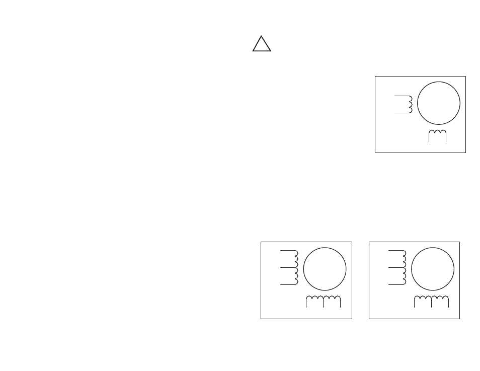
Six lead motors can be connected in series or center tap. In series mode, motors
produce more torque at low speeds, but cannot run as fast as in the center tap
configuration. In series operation, the motor should be operated at 30% less than
the rated current to prevent overheating. Winding diagrams for both connection
methods are shown below.
Note: NC means not connected to anything.
You must now decide how to connect your
motor to the drive.
Four lead motors can only be connected
one way. Please follow the sketch at the
right.