Technical specifications, Introduction – Applied Motion 3540i User Manual
Page 3
Technical Specifications
-18-
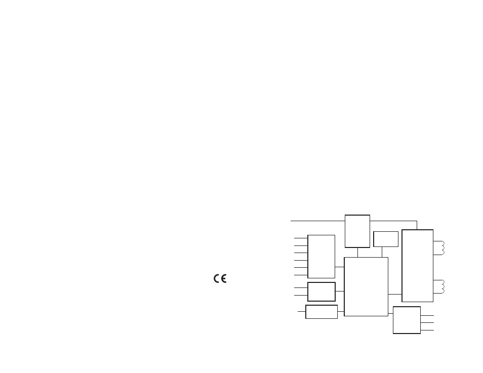
Block Diagram
-3-
Dual, MOSFET H-bridge, 3 state, pulse width modulated
switching at 20 kHz. 0.2 - 3.5 amps/phase output current,
software selectable. 147 watts maximum output power.
Automatic idle current reduction (software programmable),
reduces current to motor when idle. Minimum motor inductance
is 0.8 mH.
Accepts 12 - 42 VDC power supply. 3.5 amps typical max load.
7A maximum power on surge.
5 - 24V, optically isolated. 2200 ohms internal resistance. Can
be configured for sinking (NPN) or sourcing (PNP) signals.
Optically isolated. 24V, 100 mA max.
13 software selectable resolutions. Steps per revolution with
1.8º motor: 2000, 5000, 10000, 12800, 18000, 20000, 21600,
25000, 25400, 25600, 36000, 50000, 50800. Waveform: pure
sine.
12800 Hz.
Constructed on black anodized aluminum chassis/heat sink.
1.5 x 3 x 5 inches overall. 12 oz. 0-70ºC ambient temp range.
Power LED. See page 17 for detailed drawing .
Power, motor: screw terminal block. Wire size: AWG 12 - 28.
I/O Signals: screw terminal block. Wire size: AWG 16 - 28.
Amplifiers
Power Supply
Inputs
Outputs
Microstepping
Motion Update
Physical
Connectors
Introduction
Thank you for selecting an Applied Motion Products motor control. We hope our
dedication to performance, quality and economy will make your motion control
project successful. If there's anything we can do to improve our products or help
you use them better, please call or fax. We'd like to hear from you. Our phone
number is (800) 525-1609 or you can reach us by fax at (831) 761–6544.
Features
• Powerful, precise and efficient mosfet driver providing up to 3.5 amps per
phase and microstepping to 50,800 steps per revolution.
• Accepts 12 - 42 VDC power supply.
• Powerful, flexible, easy to use indexer.
• Connects by a simple cable to your PC for programming (cable included).
• Microsoft Windows-based software for easy set up and programming.
• Eight inputs for interacting with the user and other equipment.
• Three outputs for coordinating external equipment.
• All I/O is optically isolated, 5 - 24 V, sinking or sourcing signals. (Except
PC/MMI port which is ±12V RS-232.)
• Sturdy 1.5 x 3 x 5 inch metal chassis.
• Screw terminal connectors for motor, DC power and I/O signals
• Optional man machine interface (MMI) allows operator to enter distances,
speeds, loop counts and more.
MOSFET
3 State
PWM
Power
Amplifier
motor phase A
motor phase B
12 - 42 VDC
INPUT1
INPUT2
INPUT3
INPUT4
CW JOG/IN5
CCW JOG/IN6
to PC/MMI
CW LIMIT
CCW LIMIT
OUT1
OUT2
OUT3
RS232
Optical
Isolation
Si
™
Microstepping
Indexer
Sequencer
eeprom
Optical
Isolation
Optical
Isolation
Internal
Logic
Supply