Wiring outputs, 3540i, Connecting to the pc – Applied Motion 3540i User Manual
Page 8
-13-
-8-
A+
A–
B+
B–
8
lead
motor
8 Leads Series Connected
8 Leads Parallel Connected
A+
A–
B+
B–
8
lead
motor
Orange
Org/Wht
Blk/Wht
Black
Red
Red/
Wht
Yel/
Wht
Yellow
Orange
Org/
Wht
Blk/Wht
Black
Red
Red/Wht
Yel/
Wht
Yel
low
Eight lead motors can also be connected in two ways: series and parallel. As
with six lead motors, series operation gives you more torque at low speeds and less
torque at high speeds. In series operation, the motor should be operated at 30%
less than the rated current to prevent overheating. The wiring diagrams for eight
lead motors are shown below.
Wiring Outputs
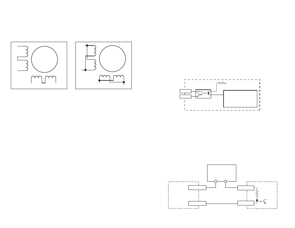
Before we discuss the output conditions, we need to talk about the circuitry. All
three 3540i outputs are optically isolated. That means that there is no electrical
connection between the indexer-drive and the output terminals. The signal is
transmitted to the output as light. What you "see" is a transistor (NPN type) that
closes, or conducts current, when the output is "low". When the output is high, the
transistor is open.
At power-up, the 3540i sets all three programmable outputs high (open circuit).
The maximum voltage between any pair of + and - output terminals is
24 volts DC. Never connect AC voltages to the 3540i output terminals.
Maximum current is 100 mA per output.
Since there is no electrical connection to the 3540i, you must provide the source of
current and voltage, typically from a power supply. You must also limit the current
to less than 100 mA so that the output transistor is not damaged. You would
normally use a resistor for this, but some loads (such as PLC inputs) limit the
current automatically.
The diagram below shows how to connect an 3540i output to an optically isolated
PLC input.
PLC
COMMON
INPUT
3540i
OUTPUT-
OUTPUT+
12-24 VDC
Power Supply
+
–
330
Ω
+5V
OUT1–
OUT1+
Optoisolator
NEC PS2502
or equiv.
3540i
Controller Chip
inside 3540i
Schematic Diagram of 3540i Output Circuit
Connecting to the PC
• Locate your computer within 6 feet of the 3540i.
• Your 3540i was shipped with a black adapter plug. It has a telephone style jack
at one end and a larger 9 pin connector at the other . Plug the large end into the
COM1 serial port of your PC. Secure the adapter with the screws on the sides. If
the COM1 port on your PC is already used by something else, you may use the
COM2 port for the 3540i. On some PCs, COM2 will have a 25 pin connector that
does not fit the black adapter plug. If this is the case, and you must use COM2, you
may have to purchase a 25 to 9 pin serial adapter at your local computer store.
• Your 3540i was also shipped with a 7 foot telephone line cord. Plug one end
into the adapter we just attached to your PC, and the other end into the RS232 jack
on your 3540i.
Never connect the 3540i to a telephone circuit. It uses the same
connectors and cords as telephones and modems, but the voltages are
not compatible.
Programming Note: Always apply power to 3540i after the Si™
Programmer software is running on your PC.