Pdo 3540 – Applied Motion PDO3540 User Manual
Page 17
-17-
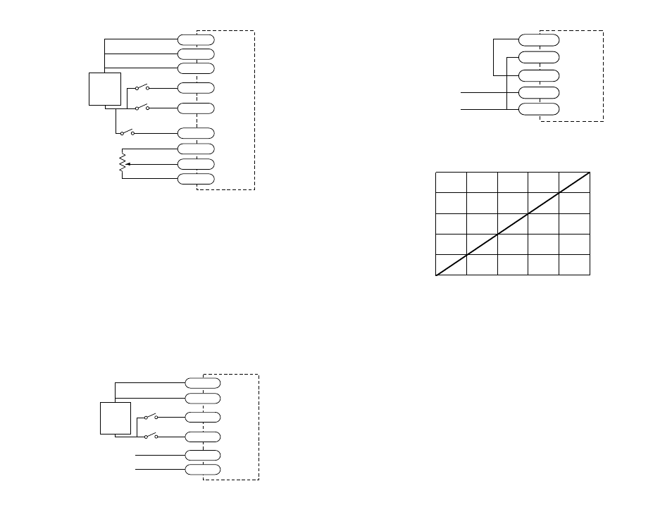
Typical Wiring for Oscillator Mode Using External Speed Control Pot
Speed Control from a 0 to 5 Volt Analog Signal
In oscillator mode, the PDO 3540 can rotate the motor at a speed proportional to an
analog voltage. The voltage must be applied to the WPR terminal. The direction of
rotation is controlled by the digital DIR input and the motor can be stopped either
by setting the analog input voltage to 0 or by turning the digital STEP signal off.
To use the PDO 3540 in this mode, set switch #8 away from the JOYSTICK label,
and set switch #7 toward the EXT SPEED label.
The HI SPEED pot sets the maximum speed (the motor speed when the analog
signal is at 5 volt DC). The range is 0 - 25 rev/sec. Wiring diagrams and a plot of
speed v. voltage are shown below and on the next page.
Wiring for Speed Control by 0 - 5 V Analog Signal (with Dir Control)
5k
Ω
pot
speed switch (closed=lo speed)
cw
ccw
PDO 3540
SPEED+
DIR-
STEP-
SPEED-
CCW
WPR
CW
DIR+
STEP+
+
5-12
VDC
SUPPLY
-
direction switch
run/stop switch
(closed=run)
0 - 5V speed signal
signal return
PDO 3540
DIR+
DIR-
STEP-
CCW
WPR
STEP+
+
5-12
VDC
SUPPLY
-
direction switch
run/stop switch
(closed=run)
-18-
Connecting Digital Inputs
The PDO 3540 contains optical isolation circuitry to prevent the electrical noise
inherent in switching amplifiers from interfering with your circuits. This arrange-
ment also allows a wide range of input voltages to be used and gives you the option
of using sinking or sourcing inputs.
A schematic diagram of the input circuit is shown on the next page.
You must supply 5 - 12 volts DC to supply current to the LEDs on the input side of
the optoisolators. 5 - 24 VDC is acceptable for the SPEED and ENABLE inputs.
You can operate the STEP and DIR inputs at 24 VDC if you add a 1000 ohm resistor
to each input. Most CMOS and open collector TTL devices are directly compatible
with this drive, as are typical PLC and proximity sensor outputs.
Wiring for Speed Control by 0 - 5 Volt Analog Signal (Unidirectional)
Speed vs Input Voltage
EXT SPEED mode, HI SPEED pot at maximum
speed (rev/sec)
0
1
2
3
4
5
0
5
10
15
20
25
0 - 5V speed signal
signal return
PDO 3540
STEP+
STEP-
CCW
WPR
CW