Applied Motion PDO3540 User Manual
Page 23
-23-
Motor
Size
Winding
Max Torque
Current
Number
inches
Connection
oz-in
Amps
5014-842
1.38 x 1.38 x 1.57
4 lead
19
1.0
HT17-068
1.65 x 1.65 x 1.30
parallel
23
1.4
HT17-071
1.65 x 1.65 x 1.54
parallel
30
1.7
HT17-075
1.65 x 1.65 x 1.85
parallel
40
1.7
5023-122
2.22 x 2.22 x 2.0
parallel
60
2.0
5023-123
2.22 x 2.22 x 3.0
parallel
100
2.5
5023-124
2.22 x 2.22 x 4.0
parallel
150
3.5
HT23-394
2.22 x 2.22 x 1.54
parallel
60
2.8
HT23-397
2.22 x 2.22 x 2.13
parallel
140
2.8
HT23-400
2.22 x 2.22 x 2.99
parallel
180
2.8
5034-348
3.38 x 3.38 x 2.50
parallel
130
3.5
Recommended Motors
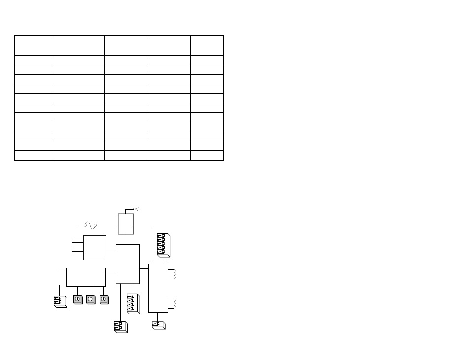
motor phase A
motor phase B
EXT
SPEED
INPUT
current
0.4 to 3.5
A/phase
ext speed
joystick
50% idle
accel
LO
speed
HI
speed
Microstep
Sequencer
Digital Oscillator
&
Joystick Interface
110 or
220 VAC
Internal
Power
Supply
power LED
MOSFET
3 State
PWM
Power
Amplifier
DIRECTION
HI/LO SPEED
ENABLE
TACH
STEP
Optical
Isolation
fuse
steps/rev
osc bypass
self test
Block Diagram
-24-
Amplifiers
Power Supply
Inputs
Tach Output
Microstepping
Dual, MOSFET H-bridge, 3 state, pulse width modulated
(PWM) switching at 20 kHz. 0.4 - 3.5 amps/phase output
current, dip switch selectable. 122 watts maximum output
power. Automatic idle current reduction (defeatable) reduces
motor current to 50% of setting after one second. Minimum
motor inductance is 0.8 mH.
Linear, toroidal transformer based for high reliability and low
noise. 100-120 or 200-240 VAC input, switch selectable. 50/
60 Hz. DC voltage at nominal line voltage: 35 VDC full load,
40 VDC no load.
Speed, Enable: optically isolated, differential 5 - 24 VDC logic.
2200 ohms internal resistor.
Step, Direction: optically isolated, differential 5 - 12 VDC
logic, 680 ohms internal resistance. (24 VDC with external
1000 ohm resistance).
Wiper: 0 - 5 VDC analog signal. Maximum recommended pot/
joystick impedance: 1K - 5K ohms. Joystick dead zone: +/- 80
mV. Potentiometer/analog signal dead zone: 40 mV.
In pulse & direction mode, motor steps on rising edge of
STEP+ input (falling edge of STEP-). 0.25
µ
sec minimum
pulse, 2 MHz maximum step rate. 1
µ
sec minimum set up
time, 50
µ
sec minimum hold time for direction signal.
Optically isolated, uncommitted (open collector, open emitter)
photo transistor. 30 VDC, 20 mA max. 100 pulses per motor
revolution, 50% duty cycle (square wave).
16 switch selectable resolutions. Steps per revolution with 1.8°
motor: 200, 400, 1000, 2000, 5000, 10000, 12800, 18000,
20000, 21600, 25000, 25400, 25600, 36000, 50000, 50800.
Waveform: pure sine. 12800 steps/rev in OSC/JOY mode.
Technical Specifications