Applied Motion PDO3540 User Manual
Page 19
-19-
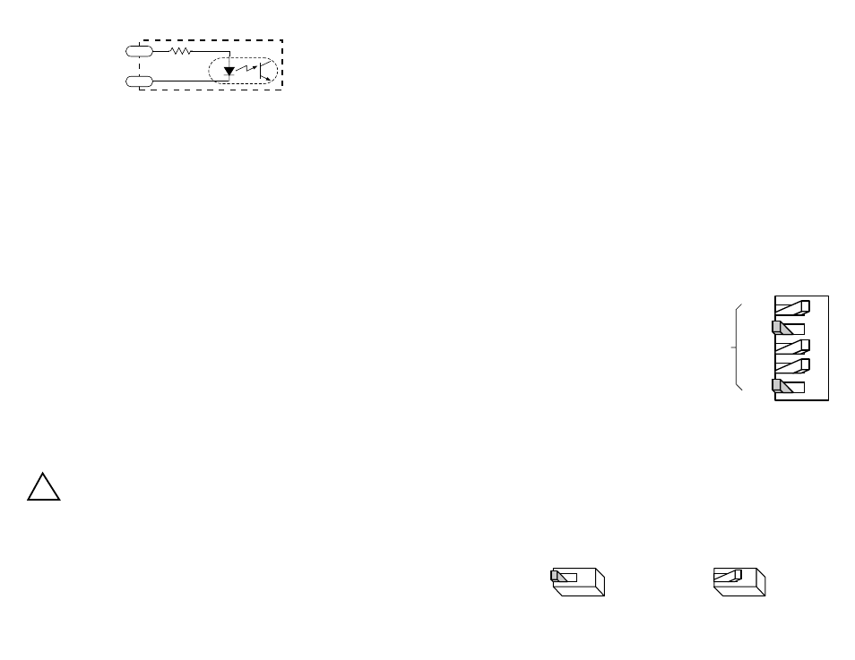
PDO 3540 Input circuit
Sinking Circuits (NPN)
If your output devices sink current, then connect the “+” terminals to your positive
power supply, and the “-” terminals to your signals (i.e. STEP-, DIR-, etc.). If you
are using a TTL circuit to drive the PDO 3540, connect the “+” terminals to your 5
volt bus. No ground connection is needed. If you are using a PLC or proximity
sensor, you’ll need a power supply.
Sourcing Circuits (PNP)
If your output devices can only source current (some PLC outputs are this way),
connect the “-” terminals to the ground of the DC power supply that powers your
output circuits. Then connect your signals to the “+” terminals (STEP+, DIR+, etc.).
Note: We refer to an input as being ON when current is flowing through the input.
A signal is OFF when no current is flowing. An input is OFF when COM and the
input terminal are at the same voltage, or when the input is left unconnected (open).
Tach Output
The Tach Out signal is provided for measuring the motor speed. It generates 100
pulses per revolution, so if you connect a frequency counter, the speed reads out in
revs/second with two decimal places.
Do not connect the Tach output to more than 24 VDC.
The current into the Tach+ terminal must not exceed 20 mA.
Enable Input
ENABLE allows the user to turn off the current to the motor by setting this signal to
logic 0. The logic circuitry continues to operate, so the drive “remembers” the step
postion even when the amplifiers are disabled. However, the motor may move
slightly when the current is removed depending on the exact motor and load
characteristics.
If you have no need to disable the amplifiers, you don’t
need to connect anything to the ENABLE input.
STEP-
STEP+
R
!
-20-
Setting Phase Current
Before you turn on the power supply the first time, you need to set the driver for the
proper motor phase current. The rated current is usually printed on the motor label.
The current you set on the PDO 3540 is the peak current, not RMS.
The PDO 3540 drive current is easy to set. If you wish, you can learn a simple
formula for setting current and never need the manual again. Or you can skip to the
table on the next page, find the current setting you want, and set the DIP switches
according to the picture.
Current Setting Formula
Locate the bank of eight switches. Five of the switches have a value of current
printed next to them, such as 0.2 and 1.6. Each switch controls the amount of
current, in amperes (A), that it’s label indicates. There is always a base current of
0.4 A. To add to that, slide the appropriate switches toward their labels. You may
need your small screwdriver for this.
Example
Suppose you want to set the driver for 2.2
amps per phase. You need the 0.4 A base
current plus another 1.8 A.
2.2 (TOTAL) = 0.4 (BASE) + 1.6 + 0.2
Slide the 1.6 and 0.2 A switches toward the
labels as shown in the figure.
Idle Current Reduction
Your drive is equipped with a feature that automatically reduces the motor current by
50% anytime the motor is not moving. This reduces drive heating by about 50%
and lowers motor heating by 75%. This feature can be disabled if desired so that
full current is maintained at all times. This is useful when a high holding torque is
required. To minimize motor and drive heating we highly recommend that you use
the idle current reduction feature unless your application strictly forbids it. Idle
current reduction is enabled by sliding switch #6 toward the 50% IDLE label, as
shown in the sketch below. Sliding the switch away from the 50% IDLE label
disables the reduction feature.
Idle Current Reduction
Idle Current Reduction
Enabled
Disabled
0.1
0.2
0.4
0.8
1.6
CURRENT
(BASE = 0.4 A)
5
4
3
2
1
50% IDLE
50% IDLE
6
6