Pdo 3540, Getting started, Connecting the ac line – Applied Motion PDO3540 User Manual
Page 6: Switch set for 110 vac, Switch set for 220 vac
-5-
Getting Started
To use your PDO 3540 motor control, you will need the following:
✔ a power cable (line cord)
✔ a compatible step motor
✔ a small flat blade screwdriver for tightening the connectors - an Applied Motion
Products screwdriver suitable for this purpose is included with your drive.
For pulse & direction mode:
✔ a source of step pulses (usually an indexer is used)
For oscillator mode:
✔ an instrument for measuring motor speed (tachometer, freq. counter or o-scope)
For joystick mode:
✔ an analog joystick (see page 25 for recommended joystick)
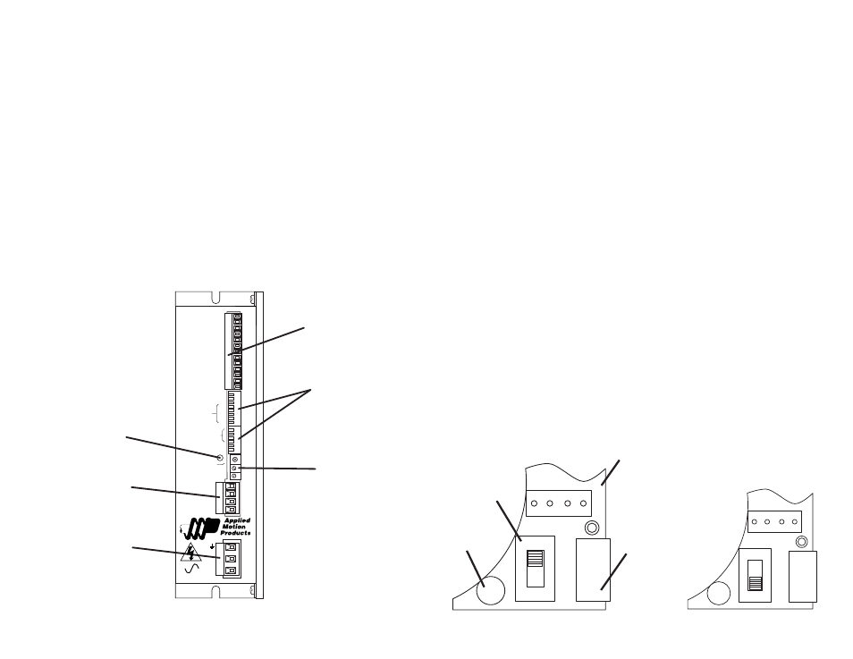
The sketch below shows where to find the important connection and adjustment
points. Please examine it now.
All mating connectors are included.
123456
123456
7
8
MOTOR
A+
A-
B+
B-
Connector*
step & direction
enable
speed
tachometer out
ext potentiometer
Power LED
Motor Connector
AC Power Connector
Dip Switches
oscillator mode
current setting
microstep resolution
idle current
Trim Pots
oscillator speed,
accel & decel
*Always use the blue & white
Applied Motion screwdriver with
this connector. Larger
screwdrivers may remove the
plastic dimples that prevent the
screws from falling out.
PDO 3540
Step Motor Driver
50% IDLE
JOYSTICK
OSC BYPASS
STEPS/REV
SELF TEST
ACCEL
EXT SPEED
0.1
0.2
0.4
0.8
1.6
CURRENT
HIGH SPEED
LOW SPEED
(BASE = 0.4 A)
POWER
DIR+
DIR–
STEP+
STEP–
EN+
EN–
SPEED+
SPEED-
TACH+
TACH–
CW
WPR
CCW
AC
POWER
-6-
Connecting the AC Line
The PDO 3540 is set for 110 VAC operation at the factory. If you use 110 VAC
power, all you need to do is install a power cord and plug it in. If you plan to use
220 VAC power, follow the instructions below.
Note: If you plan to hard wire the
PDO 3540 to AC power, consult a qualified electrician and observe all building and
electrical codes. AC power can be dangerous.
220 VAC Instructions
In order to use 220 volts, you’ll need to change a fuse and a switch setting inside
the case.
• Remove all mating connectors from the drive.
• Set the drive on it’s widest side, so that you can read
PDO 3540 Step Motor
Driver
properly.
• Remove the four (4) phillips head screws that mount the chassis sheet metal to
the chassis heat sink. See page 17 for a mechanical outline of the drive.
• The 110/220 switch is located near the position of the AC power connector, next
to the toroidal transformer (see sketch below).
• For 220 VAC operation slide the switch towards the bottom of the drive, or
towards the transformer end of the drive. The position of the switch is labeled on
the PC board also, “230” being for 200-240 VAC operation, and “115” for 100-120
VAC operation.
• Replace the fuse next to the switch with the 220 VAC fuse that came with the
drive. See technical specifications on page 25 to order more fuses.
• Replace the drive’s cover and assembly screws.
230
115
SW1
CN1
PC Board
AC Power
Connector
Fuse
110/220 VAC
Switch
Switch set for 110 VAC
230
115
SW1
CN1
Switch set for 220 VAC