Connecting the motor, 4lead motor, 6lead motor – Applied Motion PDO3540 User Manual
Page 7
-7-
Installing an AC Line Cord
Remove about 5 mm (3/16 inces) of insulation from each of the three wires of your
line cord. (That’s right, three wires. For safety, always use a three wire power cord
on anything with a metal case). Depending on where you got your power cord, it
may have black, white and green wires, or brown, white and green wires.
The AC power plug that was shipped with your PDO 3540 might be one of two
types. The “old style” is shown below, on the left. The “new style” , which comes
with an insulating rubber boot, is shown below, on the right.
Make sure you follow the proper sketch for you connector style.
Always unplug the line cord from the wall before attaching
it to the PDO 3540.
•Connect the black or brown wire to the PDO 3540 “L” terminal of the AC power
connector. That is the line, or “hot” connection.
•Connect the white or blue wire to neutral, the “N” terminal.
•Finally, and most importantly, connect the green wire to the “GND” terminal. That
connects the PDO 3540 metal enclosure and DC power supply ground to earth
ground.
!
k
c
a
l
b
e
ti
h
w
n
e
e
r
g
To Earth Ground
To Neutral
To Line (Hot)
To Earth Ground
To Neutral
To Line (Hot)
green
blac
k or brown
whit
e or blue
"Old Style"
AC Power Plug
"New Style"
AC Power Plug
-8-
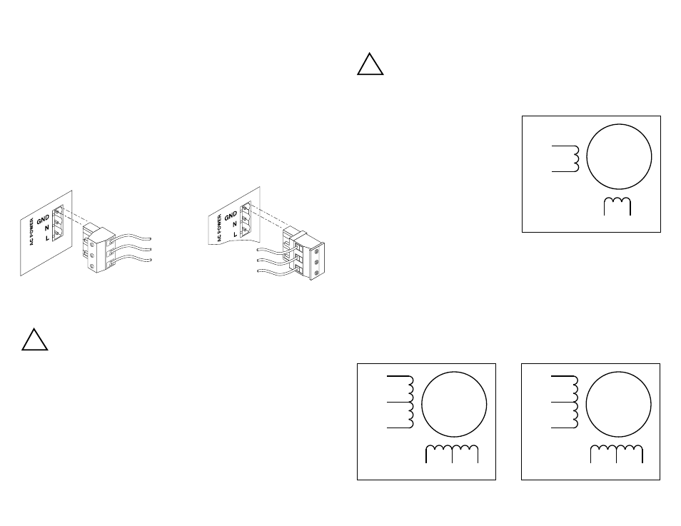
Connecting the Motor
Secure any unused motor leads, insulate exposed conductors.
Never connect motor leads to ground or to a power supply.
Never connect or disconnect the motor to the driver when the AC
power is on.
You must now decide how to connect your
motor to the drive.
Four lead motors can only be connected
one way. Please follow the sketch at the
right.
Six lead motors can be connected in series or center tap. In series mode, motors
produce more torque at low speeds, but cannot run as fast as in the center tap
configuration. In series operation, the motor should be operated at 30% less than
the rated current to prevent overheating. Wiring diagrams for both connection
methods are shown below.
!
Note: NC means not connected to anything.
A+
A–
B+
B–
4
lead
motor
Red
Blue
Yellow
White
4 Leads
A+
A–
NC
B+
B–
NC
6
lead
motor
Red
Black
Red/
Wht
Green
Grn/Wht
White
A+
A–
NC
B+
B–
NC
6
lead
motor
Grn/Wht
White
Green
Red
Red/
Wht
Black
6 Leads Series Connected
6 Leads Center Tap Connected