Connecting input signals, Connector pin diagram, Connection examples: step & dir – Applied Motion STR4 User Manual
Page 13: Internal circuit diagram, 13 str4/8 hardware manual, Step+ step, En+ en, Fault
13
STR4/8 Hardware Manual
920-0030J
5/12/2015
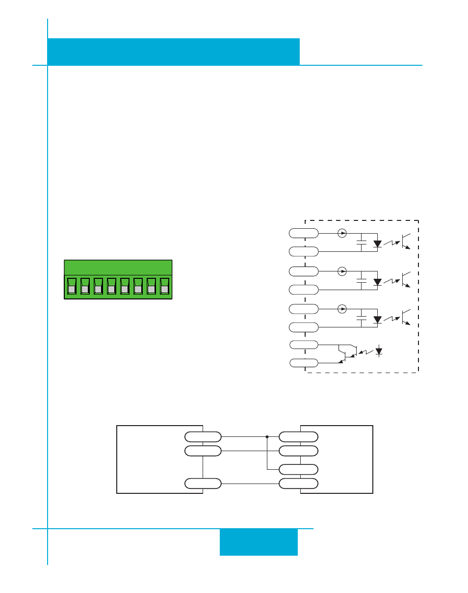
Connecting Input Signals
The STR drives have three inputs:
• STEP: a high speed digital input for step pulse commands, 5-24 volt logic
• DIR: a high speed digital input for the direction signal, 5-24 volt logic
• EN: a 5-24V input for removing power from the step motor. When the EN input is activated
the motor is disabled. Activating then de-activating the EN input clears alarms and faults, and
re-enables the motor in the case of drive faults.
Connector Pin Diagram
Internal Circuit Diagram
STEP+ STEP
–
DIR
–
EN+ EN
–
FAULT
+
FAULT
–
DIR+
inside drive
220 pF
STEP+
STEP-
220 pF
DIR+
DIR-
220 pF
EN+
EN-
FAULT+
FAULT-
Connection Examples: STEP & DIR
Connecting to indexer with Sourcing Outputs
STR
COM
DIR-
DIR
DIR+
STEP-
STEP
STEP+
Indexer
with
Sourcing
Outputs