Four-wire configuration, 17 stm23 hardware manual – Applied Motion STM23C-3CE User Manual
Page 17
NOTE: To use the STM23 RS-422/485 version with the ST Configurator software, the STM23 must be con-
nected to the PC in the four-wire “point to point” configuration (see below) and configured one axis at a
time.
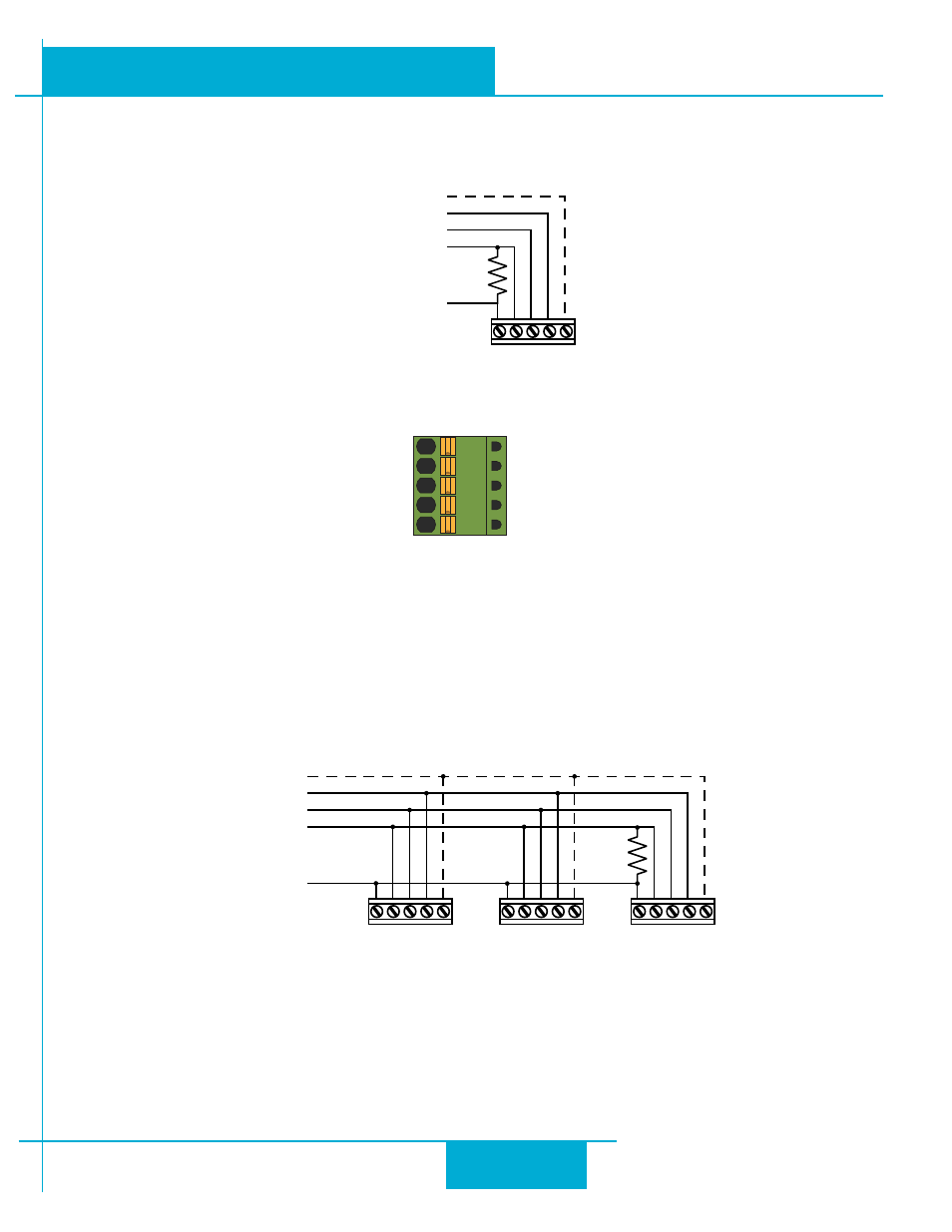
RS-422/485 4–wire “Point to Point” Wiring
RS-422/485 Connector diagram
Four-Wire Configuration
Four-wire systems utilize separate transmit and receive wires. One pair of wires must connect the host’s transmit signals to
each drive’s RX+ and RX- terminals. The other pair connects the drive’s TX+ and TX- terminals to the host’s receive signals.
A logic ground terminal is provided on each drive and can be used to keep all drives at the same ground potential.
This terminal connects internally to the DC power supply return (V-), so if all the drives on the RS-422/485 network are
powered from the same supply it is not necessary to connect the logic grounds. One drive’s GND terminal should still be
connected to the host ground.
RS-422/485 4–wire system
NOTE: a 120 ohm terminating resistor is required at the end of a four wire network.
NOTE: If the PC does not have an RS-422/485 serial port, a converter will be required.
+Rx- +Tx- GND
+Rx- +Tx- GND
+Rx- +Tx- GND
to Host Tx+
to Host Tx-
to Host Rx+
to Host Rx-
to Host GND
Drive 1
Drive 2
Drive n
120
GND
TX–
TX+
RX–
RX+
+Rx- +Tx- GND
to Host Tx+
to Host Tx-
to Host Rx+
to Host Rx-
to Host GND
STM24
17
STM23 Hardware Manual
920-0021F
2/14/2012