Stm23 inputs and outputs, 28 stm23 hardware manual – Applied Motion STM23C-3CE User Manual
Page 28
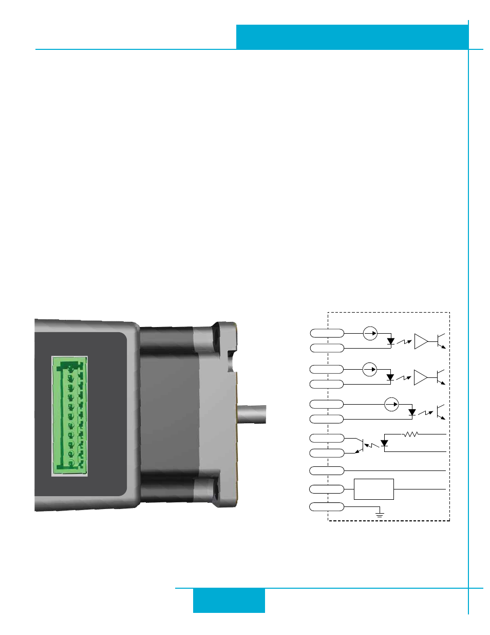
STM23 Inputs and Outputs
The STM23 drives include 3 digital inputs and 1 analog input
(no analog input on STM23C models)
.
• Two high speed digital inputs, 5-24 volt logic, labeled STEP (or IN1) and DIR (or IN2), for commanding posi-
tion. Pulse & direction, CW/CCW pulse, and A/B quadrature encoder signals can be used as position com-
mands with these inputs. The STEP/IN1 and DIR/IN2 inputs can also be connected to sensors, switches and
other devices for use with streaming SCL and Q programming commands such as Wait Input (WI), Seek Home
(SH), Feed to Sensor (FS), etc. When not being used for commanding position, these inputs can also be used
for CW/CCW end-of-travel limits, CW/CCW jog inputs, or Run/stop & direction velocity-mode inputs.
NOTE:
the available functionality of these inputs is determined by the STM23 control option (S, Q, C or IP) as well as
the motion control mode selected in ST Configurator.
• One digital input, 5-24 volt logic, labeled EN (or IN3), which can be used for motor enable/disable and/
or alarm reset. It can also be connected to a sensor, switch or other device for use with streaming SCL and Q
programming commands such as Wait Input, Seek Home, Feed to Sensor, etc.
• One analog input, 0-5 volt logic, labeled AIN, which can be used as an analog velocity or position command.
It can also be used with streaming SCL and Q programming commands such as Wait Input, Seek Home, Feed to
Sensor, etc.
NOTE: The analog input is not available on STM23C (CANopen) models.
Connector Pin Diagram - STM23
STEP+
STEP-
DIR+
DIR-
EN+
EN-
OUT+
OUT-
+5V
AIN
GND
RES
inside drive
STEP+
STEP-
I/O
Connec
tor
DIR+
DIR-
EN+
EN-
OUT+
OUT-
AIN
GND
Signal
Conditioning
+5V
50ma Limit
28
STM23 Hardware Manual
920-0021F
2/14/2012