Block diagram - stm23c, 6stm23 hardware manual – Applied Motion STM23C-3CE User Manual
Page 6
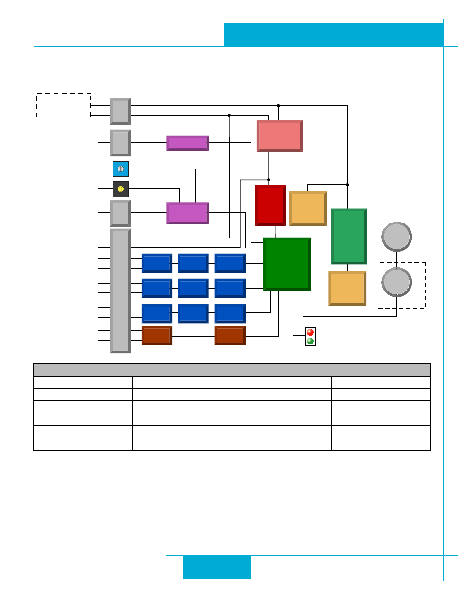
12-70 VDC
External
Power Supply
Voltage &
Temp
Monitor
motor
encoder
encoder
5 Volt DC
Power Supply
DSP
Driver
Controller
3.3VDC
Logic
Supply
+
IN1+
Status
IN1-
IN2+
IN2-
IN3+
IN3-
OUT+
OUT-
GND
GND
+5VDC
+5V
RS-232
Configuration
Port
-
Optional
Power Conn
Comm Conn
I/O Connector
RS-232
CANopen
Network
CAN Conn
CANopen
Controller
Digital
Filter
Optical
Isolation
Software
Filter
Digital
Filter
Optical
Isolation
Software
Filter
Digital
Filter
Optical
Isolation
Software
Filter
Optical
Isolation
Software
Filter
Over-
Current
Monitor
MOSFET
PWM
Power
Amplifier
Node ID
Bit Rate
4
3
21
0 F
E D C B A
9 8
76
5
5
0
4
9
3
8
2
7
1
6
Block Diagram - STM23C
I/O Functions (configure in software)
IN1
IN2
IN3
OUT
Clockwise Limit
Counterclockwise Limit Home Sensor
Fault
General Purpose Input
General Purpose Input
Enable Input
Brake
General Purpose Input
Motion
Tach
General Purpose Output
6
STM23 Hardware Manual
920-0021F
2/14/2012