Block diagram - stm23s/q/ip, 5stm23 hardware manual, Stm23s/q/ip – Applied Motion STM23C-3CE User Manual
Page 5: I/o configurations
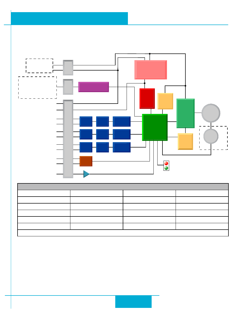
Block Diagram
MOSFET
PWM
Power
Amplifier
12-70 VDC
External
Power Supply
Voltage
Temp
Det.
Over
Current
Det.
motor
encoder
5 Volt DC
Power Supply
DSP
Driver
Controller
3.3VDC
Internal
Logic
Supply
STM23S/Q/IP
Optical
Iso
I/O Connector
+
Optical
Iso
Optical
Iso
STEP+
+5VDC (50ma Max)
GND
Digital
Filter
Digital
Filter
Digital
Filter
Software
Filter
Software
Filter
Software
Filter
STEP (5 to 24 Volts)
: Step Input
: Jog CW
: Limit CW
: Start/Stop
: General Purpose
DIR (5 to 24 Volts)
: Direction Input
: Jog CCW
: Limit CCW
: General Purpose
EN (5 to 24 Volts)
: Enable Input
: Reset Input
: Change Speed
: General Purpose
I/O Configurations
Status
AIN
Optical
Iso
RS-232 or RS-485
or Ethernet
Comm Conn
Power Conn
GND
+5V
STEP-
DIR+
DIR-
EN+
EN-
OUT+
OUT-
RS-232
TX, RX, GND, +5V
or
RS-485
RX+, RX-, TX+, TX-, GND
or 100 Mbit Ethernet
-
OUT (30V, 40ma)
: Brake Output
: Alarm Output
: Motion Output
:Tach Output
: General Purpose
Optional
Block Diagram - STM23S/Q/IP
I/O Configurations
STEP (5 to 24 Volts)
DIR (5 to 24 Volts)
EN (5 to 24 Volts)
OUT (30V, 40mA)
Step Input
Direction Input
Enable Input
Brake Output
Jog CW
Jog CCW
Reset Input
Alarm Output
Limit CW
Limit CCW
Change Speed
Motion Output
Start/Stop
General Purpose
General Purpose
Tach Output
General Purpose
General Purpose
5
STM23 Hardware Manual
920-0021F
2/14/2012