Unit terminals, Cvm-c5 instruction manual – CIRCUTOR CVM-C5 Series User Manual
Page 8
The power and voltage measuring circuit must be connected with cables that have a mini-
mum cross-section of 1mm
2
.
The secondary line of the current transformer will have a minimum cross-section of 2.5
mm
2
.
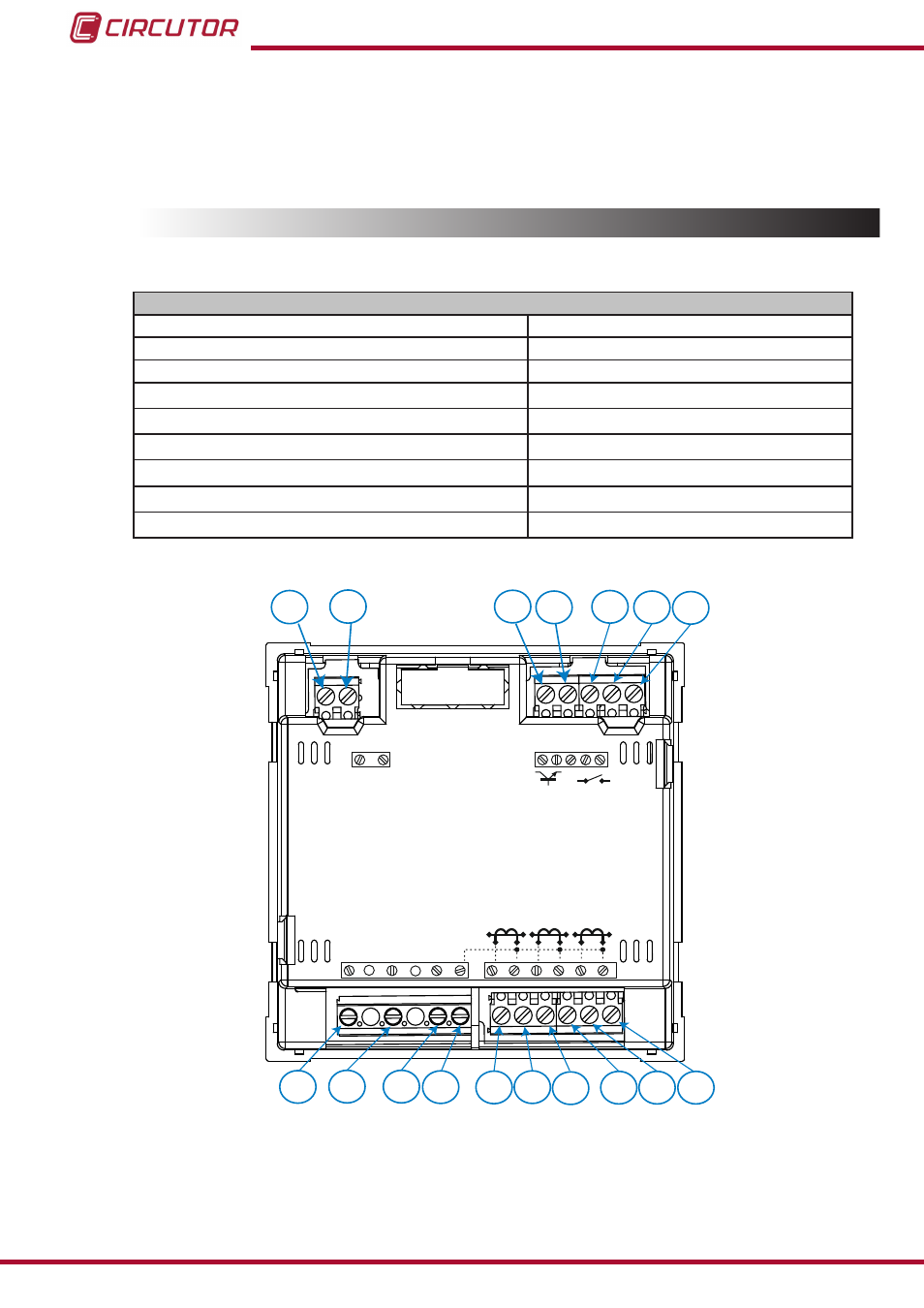
3.3.- UNIT TERMINALS
Table 2:List of CVM-C5 terminals�
Unit terminals
1 : Auxiliary Power Supply
10: V
L3
, L3 voltage input
2: Auxiliary Power Supply
11: N, neutral
3: SO+, Transistor output
12: S
1
, L1 current input
4: SO-, Transistor output
13: S
2
, L1 current input
5: Not connected
14: S
2
, L1 current input
6: Digital input
15: S
2
, L2 current input
7: Digital input
16: S
1
, L3 current input
8: V
L1
, L1 voltage input
17: S
2
, L3 current input
9: V
L1
, L1 voltage input
1
2
3
4
5
6
7
8
9
10 11
12 13 14
15 16 17
POWER SUPPLY
INPUT
S0+ S0-
OUTPUT
S1
S2
S1
S2
S1
S2
L1
P1
P2
L2
L3
300V ~
Ph-N
Ph-Ph
520V ~
N
V
L3
L2
V
L1
V
P1
P2 P1
P2
Figure 1: CVM-C5 terminals�
8
CVM-C5
Instruction Manual