Installation, Unit terminals – CIRCUTOR CEM-C10 series User Manual
Page 9
Advertising
3.2.- INSTALLATION
On the side of the unit are all of the indications adjusted to the CEI 62052-11 standard.
The unit is installed on a DIN rail. All connections are located inside the electric panel.
Terminals, opening covers or removing elements can expose parts that are
hazardous to the touch while the unit is powered. Do not use the unit until it is
fully installed.
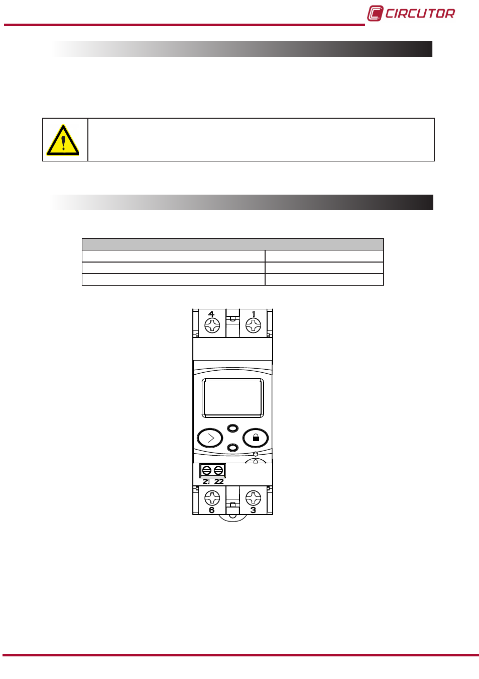
3.3.- UNIT TERMINALS
Table 3:List of CEM-C10 terminals�
Unit terminals
1 : L, Input, connected to the mains phase
6: LOAD, Output
3: LOAD, Output
21: impulse output (Collector)
4: N, Input, connected to neutral
22: Impulse output (Emitter)
Figure 1:Terminals of the CEM-C10�
9
Instruction Manual
CEM-C10
Advertising