Z5421 connector plate xa, neg. splay, Z5420 load eyebolt, Setting the splay angle – d&b xA-Series User Manual
Page 11
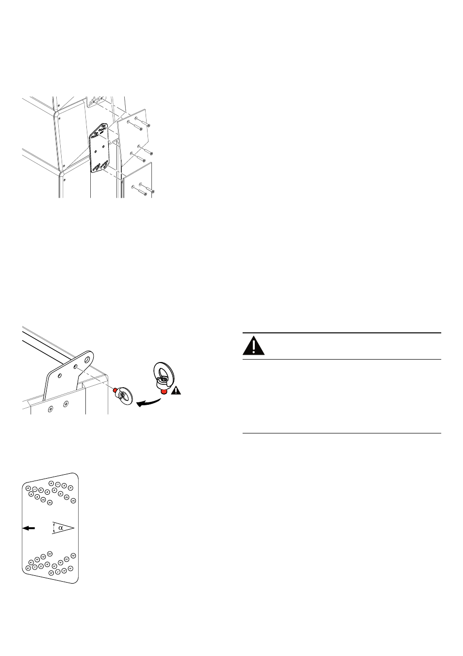
2.2.9. Z5421 Connector plate xA, neg. splay
Intended use
The connector plate is used in ground stack setups to apply a
downtilt (negative splay) to the first TOP cabinet.
The connector plate can also be used in mixed vertical arrays to
apply either an uptilt to the first TOP cabinet below a SUB cabinet
or a downtilt to the first TOP cabinet above a SUB cabinet.
Angles can be set to 0°, 1°, 2°, 4°, 6° or 9°.
2.2.10. Z5420 Load eyebolt
Intended use
The Z5420 Load eye bolt is rotatably supported and is used to
suspend the array in conjunction with the Z5413 Flying bar
connector plate xA and the Z5419 Load bar xA.
It can also be used to attach a second pickpoint between adjacent
cabinets in the lower part of the array or at the end of the array
acting as a pullback anchor device together with the Z5419 Load
bar xA, if required.
Assembly
CAUTION!
Potential risk of loosening of the fixing screw.
The integrated fixing screw of the eyebolt is rotatably supported
and therefore cannot be secured against loosening using a spring
or lock washer. To prevent the screw from loosening, an
appropriate securing glue such as "Loctide
®
" must be used.
When attaching the eyebolt, handtighten the screw using a 5 mm
Allen hex key. Do not use any extension tool as this might apply
too much torque and cause an overload on the fixing screw.
2.3. Setting the splay angle
The procedure of setting the splay angles between adjacent
cabinets (TOP or SUB cabinets) is the same for all connector plates
of the xA-Series. For this purpose, the connector plates are
equipped with a hole grid at each end.
To set the desired splay angle, use the respective pair of holes on
the connector plate for the upper and for the lower cabinet.
A correspondingly labeled diagram of the connector plate's hole
grids and possible angle settings is provided in the following
section (Þ Chapter 2.4. "Connector plate hole grids"
The following graphics show example settings for each of the
connector plates, indicating the holes to be used and the set splay
angles.
d&b xA-Series, Rigging manual (1.1 EN)
11