Connector plate hole grids – d&b xA-Series User Manual
Page 13
Advertising
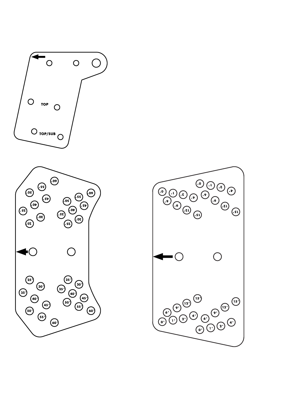
2.4. Connector plate hole grids
In the following, the hole grids of the xA connector plates are
labeled with the corresponding angle settings.
Note:
–
The graphics are not to scale.
–
The arrow indicates the mounting direction of the
connector plate toward the front of the respective cabinet.
Fig. 6: Z5416 Connector plate 10A
Fig. 7: Z5417 Connector plate 10AL
Fig. 5: Z5413 Flying bar connector plate xA
d&b xA-Series, Rigging manual (1.1 EN)
13
Advertising
See also other documents in the category d&b Receivers and Amplifiers:
- D12 Hardware (28 pages)
- D12 Software (36 pages)
- D80 (84 pages)
- D6 Hardware (24 pages)
- D6 Software (32 pages)
- D80 Touring rack NEMA L21-30 (15 pages)
- J-Series (34 pages)
- T-Series (44 pages)
- TI 385 d&b Line array design (54 pages)
- Y-Series (46 pages)
- Vi (37 pages)
- Z5053 Ci90 Bracket connector (10 pages)
- Z5017 TV spigot HD (6 pages)
- Z5024 Loudspeaker stand adapter (6 pages)
- Z5038 Fixing plate M10 (6 pages)
- Z5048 (4 pages)
- Z5056 M4 Flying bracket (6 pages)
- Z5057 M6 Flying bracket (6 pages)
- Z5091 Ci Flying bracket (6 pages)
- Z5147 Rota Clamp (8 pages)
- Z5350 E8 Flying bracket (6 pages)
- Z5351 E8 Horizontal bracket (6 pages)
- Z5352 E12 Flying bracket (6 pages)
- Z5353 E12 Horizonal bracket (6 pages)
- Z5356 E5 Ball joint adapter (7 pages)
- Z5355 E12 (10 pages)
- Z5371 T Flying bracket (8 pages)
- Z5372 T Horizontal bracket (8 pages)
- Z5373 T Cluster bracket (10 pages)
- Z5374 Ti Flyingadapter (10 pages)
- Z5375 T Base plate (8 pages)
- Z5377 E6 Swivel bracket (6 pages)
- Z5378 E6 Horizontal bracket (6 pages)
- Z5385 V Flying adapter (11 pages)
- Z5386 V Stack adapter (7 pages)
- Z5389 Bi6-SUB Horizontal bracket (10 pages)
- Z5394 Y Flying adapter (13 pages)
- Z5396 Y Base plate (10 pages)
- Z5397 YP Swivel bracket (10 pages)
- Z5398 YP Horizontal bracket (12 pages)
- Z5399 YiP Mouting bracket (8 pages)
- Z5401 Wall mount S (11 pages)
- Z5403 Wall mount (17 pages)
- Z5406 Flying bracket (13 pages)