9 led status – KBC Networks ESML6-FL2 User Manual
Page 11
Ethernet Switch User Manual
Inst_manual_hw-ESML6-FL2-Rev_1010
Copyright © KBC Networks Ltd.
Page 11 of 20
www.kbcnetworks.com
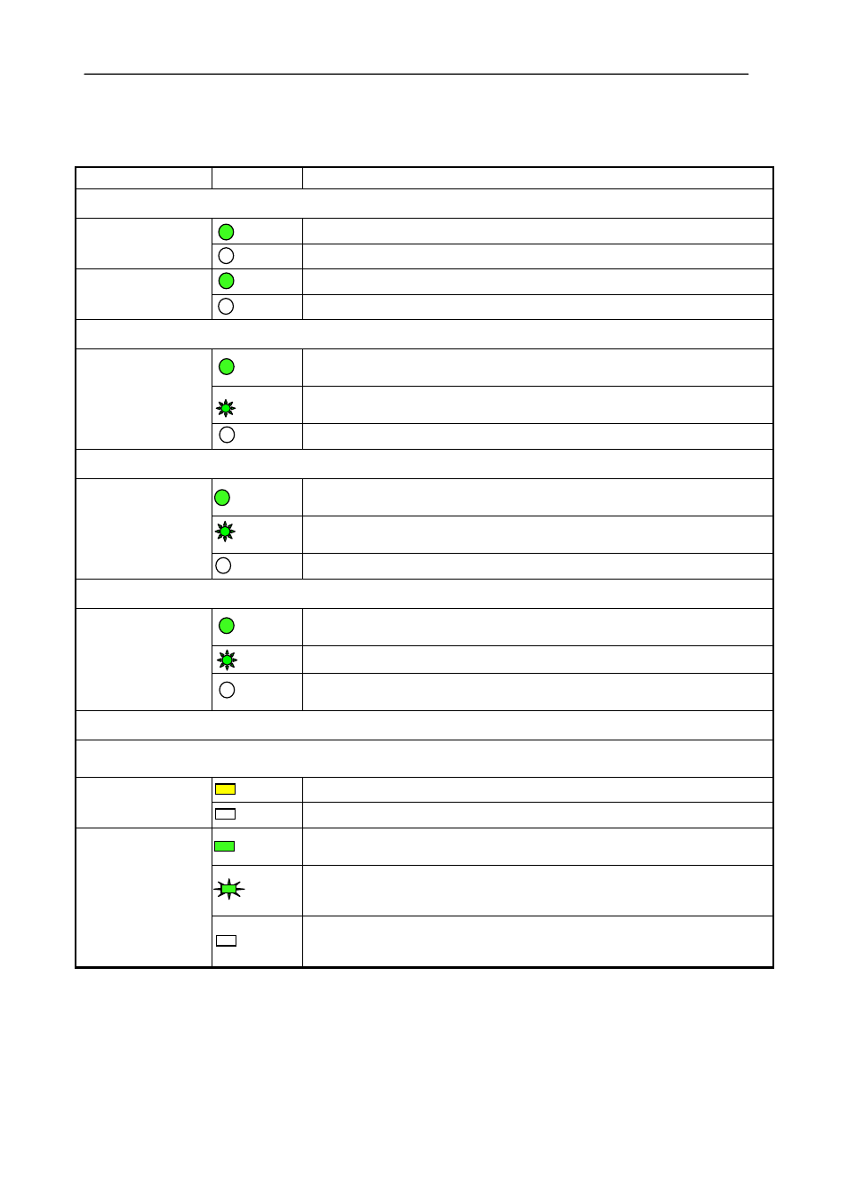
2.9 LED Status
LED
Status
Description
Power
POWER 1
ON
24Vdc power is supplied to POWER 1 input
OFF
No power is supplied to POWER 1 input
POWER 2
ON
24Vdc power is supplied to POWER 2 input
OFF
No power to the unit t POWER 2 input
Port 4 & 8 Status
RUN
(left LED)
ON
Ports 4 & 8 are set as redundant mode and the switch is set as a
master
FLASH Port 4 & 8 are set as redundant mode and the switch is set as slave.
OFF
Port 4 & 8 are set as straight through mode
Port 1 & 2 Status
RUN
(right LED)
ON
Ports 1 & 2 are set as redundant mode and the switch is set as a
master
FLASH Port 1 & 2 are set as redundant mode and the switch is set as slave.
OFF
Port 1 & 2 are set as straight through mode
Fiber Port LED (4 & 8)
LINK/ACT
Left port 4
Right port 8
ON
Effective network connection has been established for the port
FLASH Data traffic is passing through the port
OFF
No effective network connection has been established for the port
Ethernet RJ45 Port Status LED
Each RJ45 Ethernet port has two indicators, a yellow lamp and a green lamp. The yellow lamp indicates
port speed, and the green lamp indicates port link state.
10/100 (Yellow)
ON
100M working status(100Base-TX)
OFF
10M working status(10Base-T)
LINK/ACT
(Green)
ON
Effective network connection has been established for the port
FLASH Data traffic is passing through the port
OFF
No effective network connection has been established for the port