3 troubleshooting, 1 self-testing, 2 twisted pair port testing – KBC Networks ESML6-FL2 User Manual
Page 13
Ethernet Switch User Manual
Inst_manual_hw-ESML6-FL2-Rev_1010
Copyright © KBC Networks Ltd.
Page 13 of 20
www.kbcnetworks.com
2.12
RS232 Console Interface
The console interface on the ESML6-FL2 is a shielded RJ45 connector based on 3-line
RS232. The switch can be connected to a 9 pin serial port of a pc using a cable with a
DM9F connector. Hyper Terminal software in Windows can be used to gain access to the
switch software in order to configure, monitor and manage the switch. For further
information on accessing the management software please see separate software
management manual for this switch.
3 Troubleshooting
3.1 Self-testing
When the device is powered on, the Power LED will be illuminated showing that there is
power to the unit. The RUN LED will be either on, flashing or off depending on the DIP
switch setting (see Figure 2.2).
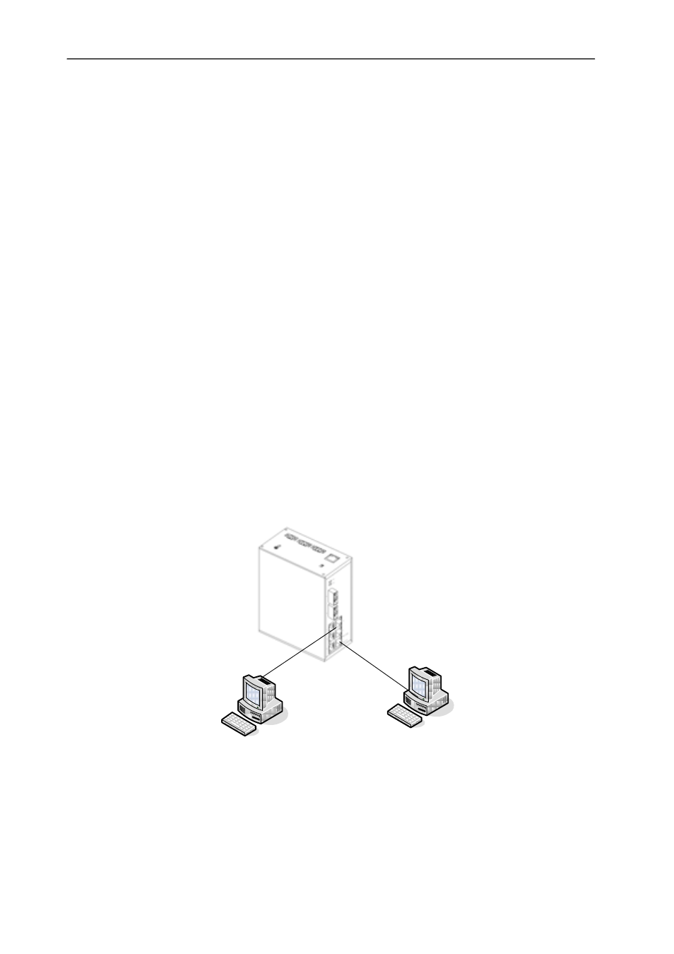
3.2 Twisted Pair Port Testing
As shown in Figure 3.1, with the switch powered on, connect two RJ45 ports from the
switch to two test computers and send the “ping” command between each computer. If
both the computers receive the complete command without packet loss and the green
LED flashes, this means that the two RJ45 ports are working correctly. Test the other
RJ45 ports as required, using the same method. During normal operation the green
LINK/ACT LED will flash to show data transfer and the yellow 10M/100M will either be off
to show 10Mbps (10BASE-T) operation or on to show 100Mbps (100BASE-TX) operation.
Testing PC
Testing PC
Figure: 3.1 Testing TP Ports