10 power input terminals, 11 alarm relay output – KBC Networks ESML6-FL2 User Manual
Page 12
Ethernet Switch User Manual
Inst_manual_hw-ESML6-FL2-Rev_1010
Copyright © KBC Networks Ltd.
Page 12 of 20
www.kbcnetworks.com
2.10
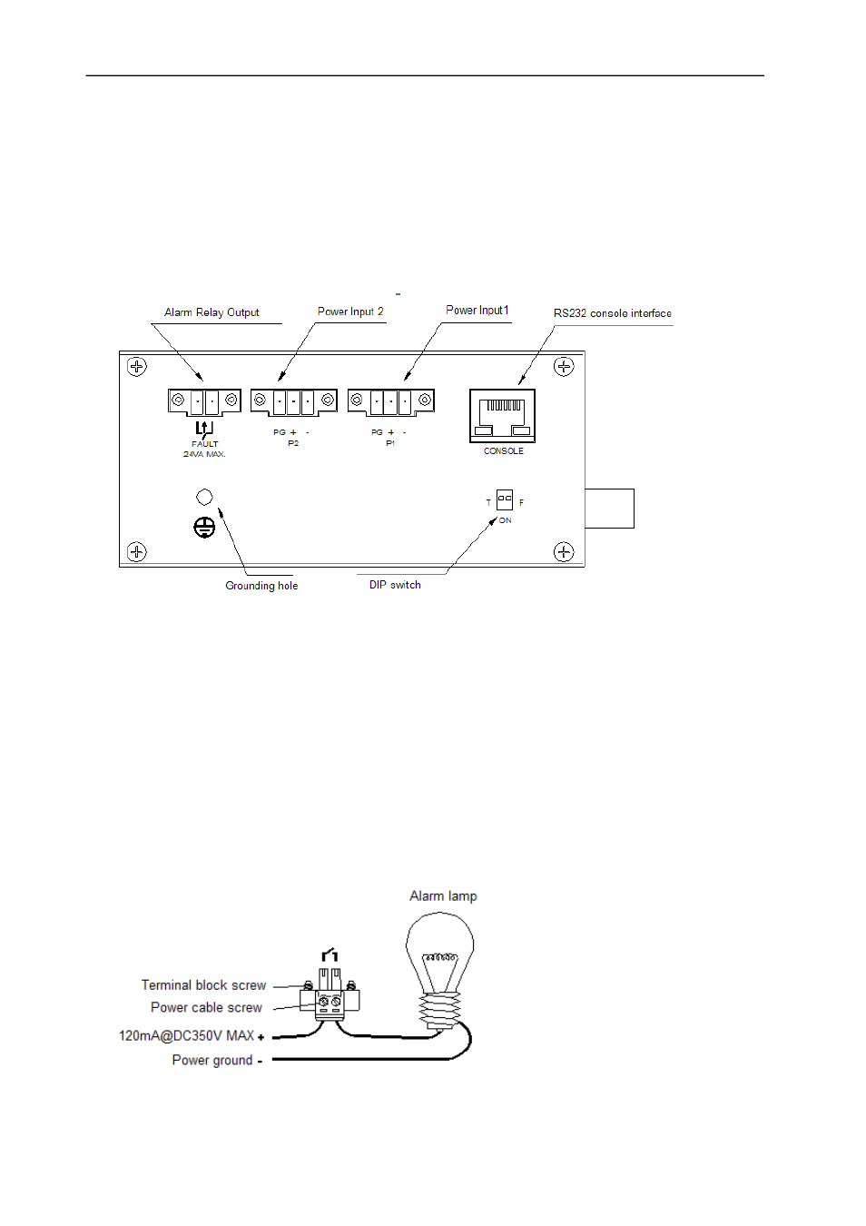
Power Input Terminals
The ESML6-FL2 has two green screw terminal blocks (Power Input 1 & Power Input
2) mounted on the top panel of the switch, see Figure 2.3. The power inputs can be
used independently or they can be connected to two separate external 24V DC
power supplies to provide redundancy. The red sleeved wire should be connected to
the +ve power input and the blue sleeved wire should be connected to the –ve
power input of the green male screw block terminal.
Figure 2.3 Power Input Terminals
2.11
Alarm Relay Output
The alarm terminal, which is also a green screw block terminal, (see Figure 2.3) has
a relay output. Under normal conditions the relay is open if there is a failure of
either of the power supplies the terminal relay becomes closed. This terminal can be
connected to other switching devices, lights or alarms to indicate that a power
source has been lost. The maximum voltage this terminal can be connected to is
350Vdc and maximum current is 120mA (see the diagram below for an example of
this kind of set up).
Figure 2.4 Alarm Lamp and Relay Output