Prm-8 callouts, Page 2 – Oxmoor PRM-8 User Manual
Page 4
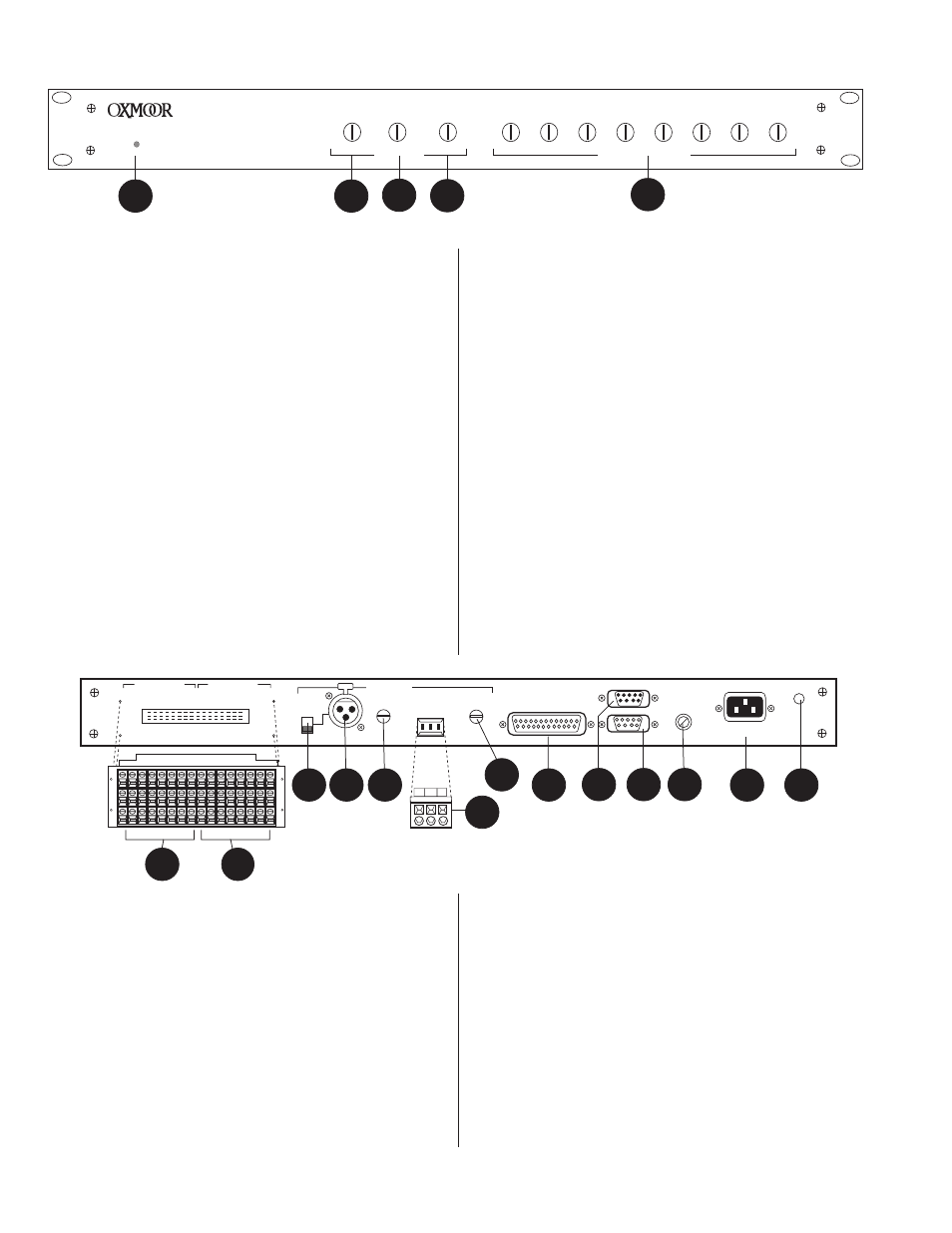
PRM-8 CALLOUTS
Page 2
PRM-8 PAGE ROUTING MODULE
POWER
DUCK
LEVEL
FADE IN
FADE OUT
PAGE LEVEL
CH1
CH 2
CH 3
CH 4
CH 5
CH 6
CH 7
CH 8
0
-80
0
5
0
5
-80
0 -80
0 -80
0 -80
0 -80
0 -80
0 -80
0 -80
0
1
2
3
4
5
10. MIC/LINE LEVEL
- Accessed through the back panel with a
small flat-blade screwdriver, adjusts the MIC/LINE input
for varying input signal levels.
11. LINE IN
- Page input, terminal block connections with
mating connector, electronically balanced input, accepts
balanced or unbalanced signals from line-level devices.
Normal input level is +4 dBu with a maximum input level
of +24 dBu.
12. LINE LEVEL
- Accessed through the back panel with a small
flat-blade screwdriver, adjusts the LINE input for varying
input signal levels.
13. CONTROL PORT
- Female, 25-pin, standard D-sub connector.
Provides connections for external switching of: Zones for
zone paging, Zone Page Enable, All Page Enable, and Zone
Page Clear. Also provides tally connections for all control
functions.
14. PA-422 IN
- Male, 9-pin D-sub connector. This port
connects to the PA-422 OUT of the MCS-MCP Master
Control Panel, an MCS-IB Interface Box or other PA-422
control devices.
15. PA-422 OUT
- Female, 9-pin D-sub connector. It is used to
carry the PA-422 data to the next PA-422 device.
16. FUSE HOLDER
- Replace only with approved type of fuse
in a rating appropriate to the mains voltage, as indicated
on back panel. (See SPECIFICATIONS).
17. POWER CONNECTOR
- Standard IEC 3-pin connector for
AC power cord. Use only with grounded (3-wire) outlets.
Cord sets are available for all world connection
standards.
18. CHASSIS GROUND POST
- A screw with a star washer
enables the installer to secure a ground wire to the
chassis.
Figure 1.0: Front Panel View
1.
POWER STATUS LED
- Indicator for AC Power On.
2.
DUCK LEVEL
- Duck level control pot, accessed through the
front panel with a small flat-blade screwdriver, adjusts the
level to which program material is attenuated during a
page. Range is from 0 (no ducking) to -80 dB.
3.
FADE IN
- Accessed through the front panel with a small
flat-blade screwdriver, sets the time required, during a
page, for the program material to be attenuated to the
level established by the DUCK LEVEL control.
4.
FADE OUT
- Accessed through the front panel with a small
flat-blade screwdriver, sets the time required for the
program material to return to its prior level upon
cessation of a page.
5.
PAGE LEVEL
- Accessed through the front panel with a
small flat-blade screwdriver, these attenuators adjust
page level, from 0 to -80 dB, in each zone individually.
6.
PROGRAM OUTPUTS
- Audio outputs, terminal block
connections with mating connector, electronically
balanced, accommodate balanced or unbalanced lines.
Recommended load impedance is 600 ohms or greater.
Maximum output level is +24 dBu.
7.
PROGRAM INPUTS
- Audio inputs, terminal block
connections with mating connector, electronically balanced,
accept balanced or unbalanced signals from line-level
devices. Normal input level is +4 dBu with a maximum input
level of +24 dBu.
8.
MIC, LINE
- Switch configures the MIC/LINE input to
accept either a microphone-level or a line-level source.
9.
MIC/LINE
- Page input, XLR-F type, Pin 2 positive,
electronically balanced, accepts balanced or unbalanced
signals. Normal input level is dependent on the MIC,
LINE switch setting. Microphone input level is -50 dBu
with a maximum input level of -20 dBu. Line input level
is +4 dBu with a maximum input level of +24 dBu.
8
7
6
5
4
3
2
1
8
7
6
5
4
3
2
1
PROGRAM OUTPUTS
PROGRAM INPUTS
PA-422 IN
CHASSIS
PA-422 OUT
CONTROL PORT
PAGE INPUTS
+
–
S
LINE
LEVEL
LINE
MIC/LINE
LEVEL
MIC/LINE
+
–
S
OXMOOR
MADE IN USA BY
OXMOOR CORPORATION
BIRMINGHAM, ALABAMA
SERIAL #
LINE
MIC
POWER
FUSE
PUSH
13
Figure 1.1: Rear Panel View
14
16
8
9
10
15
17
18
6
7
12
11